The Basics

Welcome to Memorial University’s Student Design Hub! Here you have access to multiple 3D printers where can bring your digital designs to life!
3D printing or additive manufacturing is a process in which solid objects are made from a digital file. The most widely used technique is Fused Deposition Modeling (FDM).FDM is the process of feeding a polymer-based material through a nozzle in which the material melts and gets extruded in a distnict pattern onto a flat surface where it will harden again. 3D printers repeat this process with many distinct and thin layers to mold the material into the desired design. The relative speed of creating these parts (a couple of hoursdepending on size, design, and infill) allows for proof of concepts to be developed rapidly, moving past 3Dmodeling, a very powerful tool tied to 3D printing. The end results used to be used exclusively for prototyping, however, due to the advancements of 3D printing technology and materials, 3D prints are being used more frequently as end products and parts.
For more detailed information please visit the sources used under Reference List
Materials
The most common materials for 3D printing are Poly Lactic Acid (PLA) and Acrylonitrile Butadiene Styrene (ABS). PLA filament is a biodegradable material that is easy to print due to its low heating requirements, however it does not possess a very high resilience to UV rays, its more suitable for parts used indoors and at around room temperature. ABS filament in the other hand requires a higher temperature to be printed, but it offers UV resilience as well as better mechanical properties in high temperature environments. There are many other materials available to print as well, depending on the printer you use. Some materials are:
Polyethylene Terephthalate Glycol (PETG)
Thermoplastic Polyurethane (TPU)
High Impact Polystyrene (HIPS)
Polycarbonate (PC)
Thermoplastic Elastomer (TPE)
Nylon
Acrylonitrile Styrene Acrylate (ASA)
Polypropylene (PP)
Polyvinyl Alcohol (PVA)
Glass Fiber or Carbon Fiber Infused
Metal or Wood Fill
Etc.
Modelling
One of the advantages of 3D printing is that very complex models can be achieved. However, when crafting your 3D model in a computer-aided design (CAD) software, such as SolidWorks, some design considerations can help ensure better results.
Resoultion: Similar to image resolution, a 3D printer has a minimum feature, analogous to a pixel in a picture, this is the smallest “dot” a 3D printer can extrude accurately and consistently. This is called the printers resolution. Resolution is divided into XY-resolution, and is influenced by factors such as nozzle diameter and the smallest movement capable of the stepper motor on the printer. Because of this, each printer can have a different minimum layer height, but a general rule of thumb is a minimum layer height of 0.2mm. Anyhting less than 0.2mm may arise consistency and accuracy issues


Orientation: Printing orientation of the 3D model can greatly improve the surface quality of the print. The figure displays the same 3D model printed horizontally and vertically. The horizontal print on the left displays a “staircase” pattern finish, while the vertically prited part on the right has a much smoother finish due to it’s logical orientation. A logically oriented part accounts for minimal overhang areas and lofts the scale vertically. When printing parts that would undergo a mechanical load, the former would support more force applied to it at the peak of the semi-dome than the latter.

Size: Each printer has maximum length, width and height in which it can print. When considering the size of your design consider the size of the print bed and the orientation of your part. If the design cannot be scaled down and is simply too big for the printer, making the prototype is seperate prints the combining with post-processing may be a viable option.
Wall Thickness: A minimum wall thickness is required for the model to be able to print and be structurally sound. This dimension would be affected if the model needs to support any force, but as a rule of thumb for ABS it is recommended to use a minimum wall thickness of 1.2mm. Different materials and printers have their own configurations. If thin wall prints are required see Thin Wall Printing in Building the Supermarine Spitfire Mk IX Plane Case Study.
Shrinkage and Assembly: When printing parts that are design to be connected to each other, keep in mind the shrinkage that the prints will undergo. This deviation of the print from the model’s nominal size is also known as dimensional accuracy and is generally around 0.1% or ±0.2mm.

Embossed and Engraved Details: Engraving refers to details added into the print (inwards), a minimum line thickness of 1 mm and a depth of 0.3 mm is recommended. By contrast, embossing are details that protrude from the printed model, a line thickness of at minimum 2.5 mm and a depth of at least 0.5 mm is advice. Engravings are usually preferred as they require much lower tolerances than embossing details.

Support Material: To be able to achieve intricate designs most 3D printers employ support materials. The most popular support method is breakaway supports. Breakaway support materials are temporary beams that are printed around your model to support overhangs or ares where the melted plastic cannot support itself until hardened. These can be broken away as soon as the print has been finished, but in certain complex geometries they tend to leave residue behind and/or are difficult to completely remove without damaging the print. This is caused if the design possess deep channels/crevices in the inside faces of the model, where no exit hole is accounted for. With that being said the difference is minimal and breakaways are the best option for the majority of prints you will complete. This is very important to keep in mind when modeling your 3D design. Every printer in the Student Design Hub uses this method of support for 3D printing. Another method to create supports is through soluable supports. Soluble support materials work the same as breakaways but instead they leave a smoother finish and are easier to remove because they are able to be dissolved in water instead of having to be broken away. However this method of support material is only available through one printer located in the Digital Design and Prototyping Lab and is a quite longer process.


Moving Parts: Support material allows for the printing of preassembled models with moving parts, for these to successfully print a minimum clearance of 0.4mm is advised, the greater the space that can be afford, the better chance the model has to print properly.

STL Format
After you have finished your design, save the SolidWorks model in the native format SolidWorks Part File (SLDPRT) as well as the Standard Triangle/Tessellation Language file format (STL) [1]. To save your model in STL format go to File>>Save as, and change the file format from SolidWorks Part (.prt;.sldprt) to STL (*.stl) in the prompted window, as shown in the image below:

The SLDPRT file stores the part as a solid model, keeping the specified details of material, color, and texture. On the other hand, an STL file stores only the information of the 3D model surface, it represents this surface as small adjacent triangles.

Once you have a STL file saved of your design you are ready for the next section of this tutorial. , Printing ^^^^^^^^
The .STL file will be imported into a slicer, a software that produces a path for the 3D printer to follow to be able to print the model. This set path is known as G-code, and it tells the printer what movements to make from the begging to the end of the print.

Eryone ER-20

How to Use the Eryone ER-20 Printer
There are a few steps involved before printing with the Eryone ER-20 printer. The first is to make sure your 3D model has been saved in STL format. Please review STL Format to learn how.
The next step is selecting a material to use in this print. The Eryone ER-20 supports 3 different materials:
Poly Latic Acid (PLA): PLA filament is a biodegradable material that is easy to print due to its low heating requirements, however it does not possess a very high resilience to UV rays, its more suitable for parts used indoors and at around room temperature.
Polyethylene Terephthalate Glycol (PETG): PETG is a more durable filament then PLA. It has good chemical resistance, flexibility, and impact resistance. As well as being good for clear prints, however this also means “post processing” such as sanding or removing supports can be much more difficult.
Thermoplastic Polyurethane (TPU): TPU is a rubber like filament offering it flexibility and versatility, however it can be more of a challenge to print.
More information on each filament can be found here
Once you have chosen a material, the next step is to upload your STL to a Slicer. In this case we will be using Simplify3D.
There are two guides to using Simplify3D: A quick guide for very easy and simple parts such as a chess piece and a detailed guide for more complex parts and different materials.
Open up Simplify3D by double clicking the icon.

You should be brought to this page.

If there is already an item(s) on the screen, please select the “Remove” button. Then click “Import”, this should bring you to file explorer where you will open up your STL.

Here is where you can view your model from different angles. By left clicking and dragging you can rotate around the model, by right clicking and dragging you can change the point of rotation. The command bar on the right side of your screen is also available for quick changes to different viewing planes, similar to SOLIDWORKS.

This command bar also lets the user position, scale or rotate their model. You can also double click your model for precise numerical changes and the ability to reset any changes.

The center and arrange button will automatically fix the orientation of your part(s) and make them fit on the bed.
When arranging your part on the bed there is a few things to take into consideration. FDM printing is done by layering melted thermoplastic on top of itself, building from the ground up. You can not print something in thin air, there needs to be something to support it. Take a look at this bracket:

The first arrangement does not work because it requires plastic to be laid down in thin air. The second arrangement will print however, you should also look at the largest FLAT surface of your model and print from there. This will assure good bed adhesion and a better chance at a successful print. The third option with a large FLAT surface to print from and no overhang is the best option for this model.
Once your part(s) are arranged on the bed, click “Edit Process Settings”. This window should appear:

This is the command center of Simplify3D, everything happens in here. In this quick guide we will not be going through all the settings but instead checking a few things to make sure everything is right before you print. If your model consists of any of the following features, then you may want to consider the Advanced Workflow.
Large Overhang (Support structures needed)
Thin Walls
Fine Details
No Large Flat Surface to Start Print From
Needs to be Especially Dense or Strong
Multiple Colours or Materials
Electronic Enclosure (Threaded Holes)
Troubleshooting
See here an example sheet.
pdf
Simple Parts Workflow
If your part is simple and does not fall under any of the above categories, then please follow the instructions below.
Once you select edit process settings this page should appear. Make sure everything in the green boxes match your screen. “Coast at End” and “Wipe Nozzle” should not be checked.

Now click the layer tab and check these settings:

Next the Additions Tab, only skirt/brim should be checked. Uncheck any other boxes if they are on.

Next is the infill tab. The offset boxes should rarely be touched but if it is not the same, use the add and remove angle buttons to navigate the boxes.

Nothing should be selected in the support tab.
For the Temperatures tab, each filament has it’s own preferred settings. You will have to change the temperature of the extruder and bed based on what brand of material you are using. these temperature settings are often found printed directly on the filament spool or can be searched up on google, You can change the temperature by double clicking the number or by using the add and remove button.


For list of common PLA temperatures please view sheet pdf
Nothing should ever be touched in the G-Code tab, but just to be sure, check these settings:

In the Scripts tab there are a few different windows. Layer Change, Retraction and Tool Change Scripts should all be blank. The Starting and Ending Scripts should look like this.


Next is the Speeds tab.

The Other tab. Filament Properties and Tool Change Retraction does not affect the print.

Bridging is subject to change
And finally, the Advanced tab.

These should all be the default settings under the “Eryone ER-20” profile however it is always good practice to check and make sure.

Select the “OK” button, the window should close. Now click “Prepare to Print!”. You should be brought to this screen where you can see how the model will be printed layer by layer.

You can also view the different features that the print has.
For a simple print there is nothing needed to do here. In the top left corner Simplify3D estimates the build time however, it is rarely accurate. A good practice is to add about 20% more time, but it may be more or less.
You now want to acquire the Micro SD card and plug it into the computer using the USB A adapter. Now click “Save Toolpaths to Disk” and transfer the SD card to the printer (Via Left side hole).
To prepare your printer and begin printing click Preparing Printer
Eryone Quick Start Material Settings
Material |
Infill (%) |
Layer Height (mm) |
First Layer Speed (mm/s) |
Speed (mm/s) |
Retraction (mm) |
Nozzle Temp. (F) |
Bed Temp. (F) |
|---|---|---|---|---|---|---|---|
PLA |
20 |
0.2 |
30 |
60 |
5 |
215 |
55 |
PETG |
20 |
0.2 |
20 |
45 |
5 |
255 |
85 |
TPU |
20 |
0.2 |
15 |
20 |
6 |
220 |
60 |
Prusa i3 MK3S+
PrusaSlicer Setup
The first step is to run the installer and follow the instructions mentioned. If you already have the PrusaSlicer installed, you can skip this step, just ensure the slicer does not need any updates.
After finishing the installation process, PrusaSlicer needs to be configured to use the Prusa i3 MK3S with the MMU2S unit:
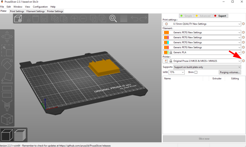
From the side menu, click the settings button next to “Printer” drop-down menu.
Click “Add/Remove presets.” This will open a new window where all the Prusa 3D printer models are listed.
Scroll to the “MK3 Family” section.
Look for the “Original Prusa i3 MK3S & MK3S+ MMU2S” entry, and check the “0.4 mm nozzle” box under it.
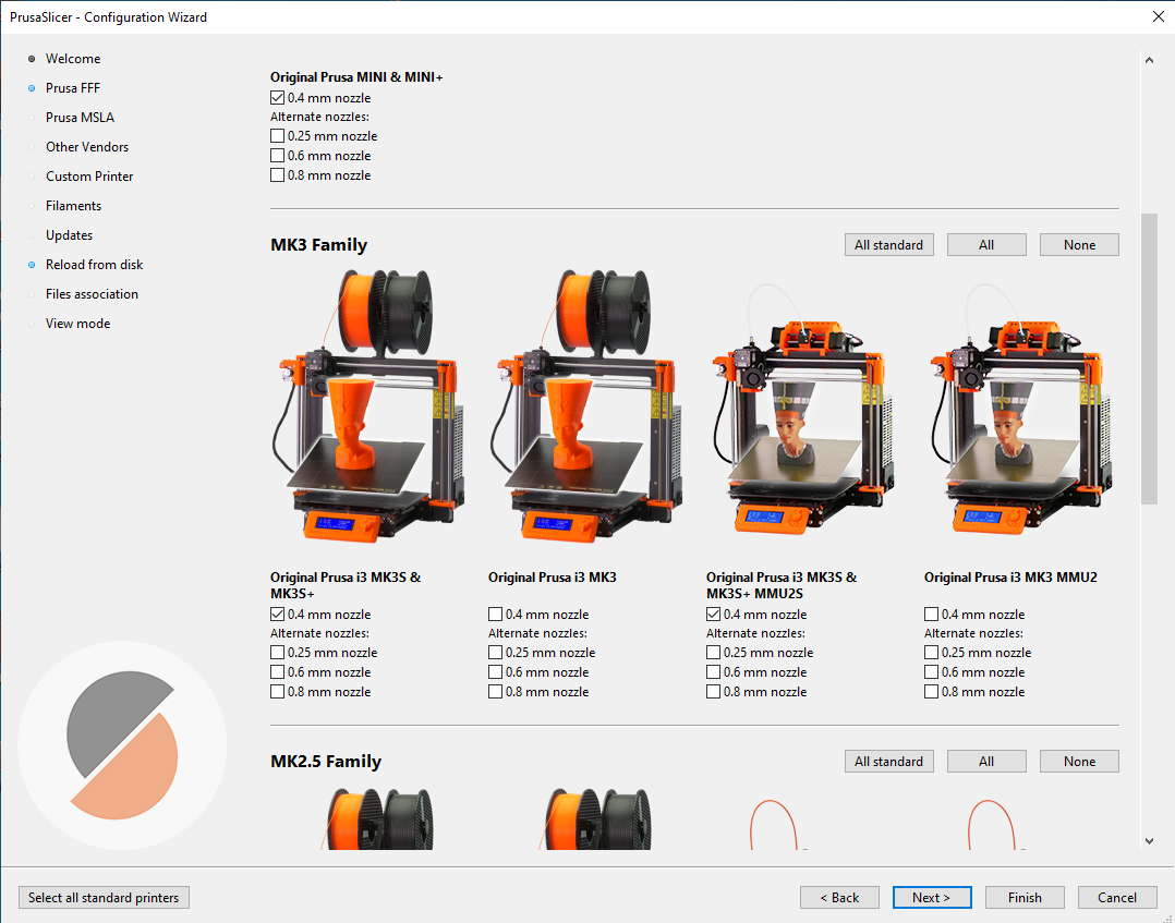
Click “Finish.”
Make sure to select “Original Prusa i3 MK3S & MK3S+ MMU2S” from the “Printer” drop-down on the side menu.
From the File menu, select Import → Import Config…
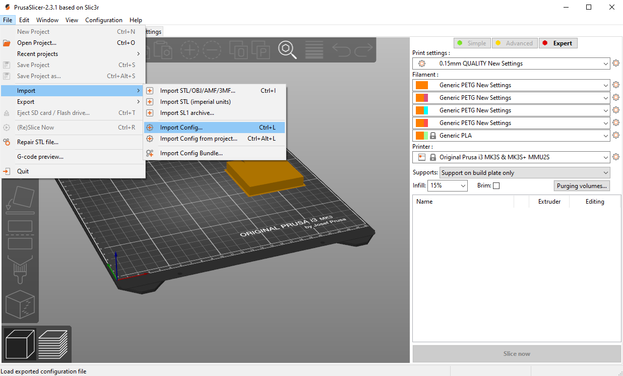
Select the configuration file you downloaded.
The last step is to set the filament type and colors to better visualize your models. There are five drop-down lists on the right side menu under “Filament:” These lists set the filament setting for each of the five MMU2S filament channels.
For PETG, choose the “Generic PETG New Settings” option for all drop-down lists. This is the setting imported from our configuration file.
Click the small orange square next to each list to change the filament color.
Note that the filament colors should match the order of the spools loaded to the MMU2S.
Now the PrusaSlicer is ready for printing.
Generating Gcode
When exporting a multi-color CAD design to STL for printing, parts with different colors will be exported to separate STL files. These files should be imported together to PrusaSlicer for the print to align correctly. For example, the multi-color penguin model below consists of three STL files with different colors. To import that:
Click Add.. from the top toolbar.
Select all the STL files for the model together.
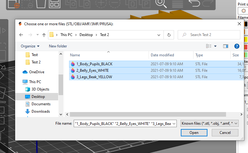
Click Ok.
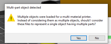
The PrusaSlicer will recognize multi-color prints and will prompt a message asking whether the files should be treated as one model or separate parts.
Select “Yes” to import the files as one model.
The model will then appear in the side menu, where every part is listed as a separate object.
For each part, choose which filament you would like that part to be printed with. Double-click the colored rectangle under “Extruder” to select the filament number.
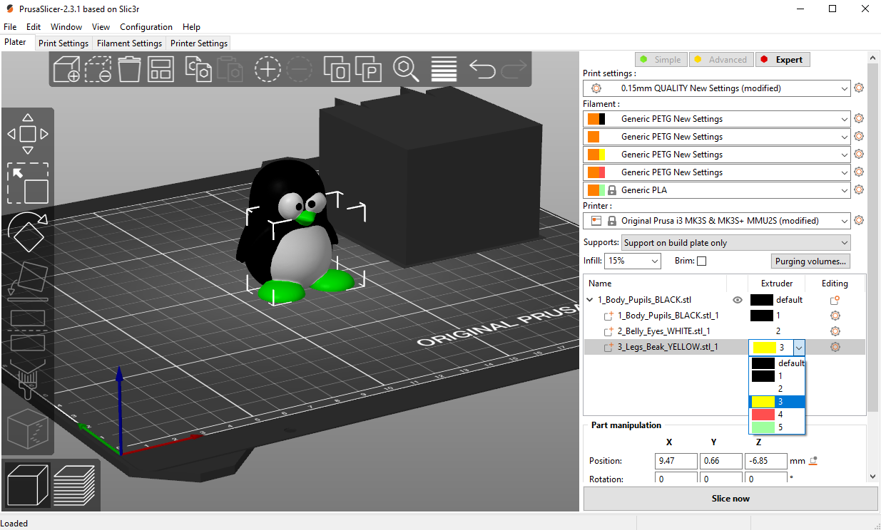
After assigning colors for all parts, click “Slice now” to generate the Gcode file. Copy that to the Prusa’s SD card.
You will notice that there is a non-removable rectangular block next to your model. This is called the “Wipe Tower.” Whenever the Prusa needs to switch from one filament to another, it extrudes some of the filament to the wipe tower to remove any remains of the last filament after loading a new color. This helps prime the filament before printing and cleans the nozzle to prevent colors from mixing.
Loading the filament
Before you begin printing, you need to load all the filament colors you need for the print. When a filament is loaded, it is not inserted all the way to the nozzle. “Loading” the filament means having it ready for the MMU2S to pull whenever it is needed. To load a filament:
Click the black knob on the Prusa.
Rotate the knob to reach the “Load Filament” option
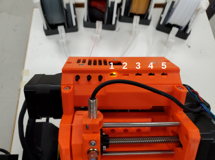
Select the number of the filament to load. Filament channels are numbered from left (number 1) to right (number 5).
If it is the first time loading, the MMU2S will make calibration moves before loading the filament.
When calibration is done, the filament selector unit will move to the channel selected, and the red LED above that channel will start blinking.
Insert the filament into the tube until it reaches the MMU2S. You will see the filament end when looking closely at the top of the MMU2S.
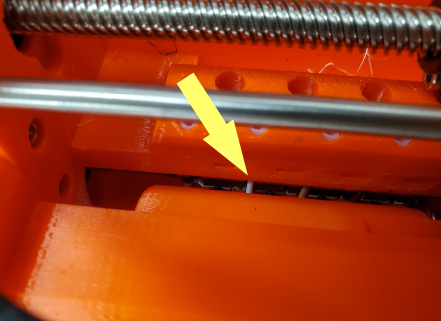
The MMU2S will pull the filament. A sensor inside the selector tells the MMU2S whether the filament has successfully reached the selector. If so, the filament will be pulled back and rest on the idler. Loading is successful in this case, and the LED will turn green.
Repeat the same procedure for all filaments.
After all filaments are loaded, go back to the main menu, select “Print from SD Card,” and choose your Gcode.
Now, you can start printing!
Troubleshooting
The MMU2S sometimes has issues with loading/unloading filament. Fortunately, the LEDs on the MMU2S help diagnose and solve most problems. Whenever there is an issue, the LEDs will blink, and a message will show on the Prusa’s LCD screen. Below is a table of the most common issues we faced and how to solve them. Check this link for a more detailed description of each problem.
Indicator |
Issue |
Solution |
|---|---|---|
One of the MMU2S LEDs is blinking slowly in red |
Problem loading filament at that channel |
Make sure the filament is inserted all the way through the tube until it hits the idler pulley. You can see the filament end at the top of the MMU2S. After that, press the middle button on the MMU2S to re-load the filament. If loading is successful, the LED will blink red-green. Press the right button to resume printing. |
One of the MMU2S LEDs is blinking fast in red |
Problem unloading filament at that channel |
Unscrew the selector filament tube blue Festo fitting and manually pull the filament out of the extruder. Cut around 10 cm of the filament, leaving part of the filament inside the selector. Screw the Festo fitting back. After that, press the middle button on the MMU2S to re-unload the filament. If unloading is successful, the LED will blink red-green. Press the right button to resume printing. |
All MMU2S LEDs blinking |
Problem with the selector or the idler |
Make sure there is no filament inside the selector. Use an Allen key to push the reset button on the side of the MMU2S. After the MMU2S restarts, click the black knob to resume printing. |
“MMU loading failed” message on the LCD while the Prusa pulls the filament to the extruder and pushes it back again multiple times. |
Problem with the extruder IR sensor not being calibrated |
On the Prusa screen, scroll to Support → Sensor Info. Unscrew the extruder filament tube blue Festo fitting, and insert a size-1.5 Allen key into the extruder’s filament tube opening. Unscrew the extruder’s chimney screws and move the chimney to the left until the Prusa’s LCD screen shows “1” next to “IR Sensor” reading, then tighten the chimney screws. Remove the Allen key and screw the Festo fitting back to place. After that, press the middle button on the MMU2S to re-load the filament. If loading is successful, the LED will blink red-green. Press the right button to resume print. For more information and illustrations, check this link. |
Advanced Workflow
Welcome to the Advanced Workflow! Please expand the Eryone ER-20 tree on the left side of your screen to view all sections.
Changing and Inserting Material
Changing the material with the Eryone printer is a very simple process. The first thing you want to do is find your selected material and bring it to the printer.
Now, you want to grab the wire cutters and the end of the filament, being very careful not to let go of the filament so it does not flick back to the spool and get tangled up. Cut the end of the filament at a 45° angle and keep hold of the end or place it back in the side spool hole.

Please read all instructions as you will need to do this even when replacing or changing filament that is already in the printer.
If there is no filament in the printer already, place the spool onto the spool holder. Grab the end of the filament that you have cut and insert it into the orange tube. Keep pushing the filament in until it reaches the golden wheel. Now you want to pinch the back of the orange clamp that encases the golden wheel and push the filament through, so that it goes past the wheel and into the next hole. If the filament goes into the next hole, continue to pinch the clamps, and push the filament all the way until it stops (hitting the start of the extruder).

If the filament is not going into the next hole and is instead going upwards toward the top of the clamp, there is a simple fix. Pull the filament back so that it is before the hole. Grab a friend or some assistance and a thin tool, such as a knife (BE CAREFUL). You will want to pinch the orange clamp and push the filament down with the knife. At this time have your friend push the filament while you push the filament down so that it goes through the hole.

If you are changing the filament you can skip this next step because the printer should do this by itself when changing filament.
Once you have the filament pushed all the way until it hits the start of the hot end, you are going to want to heat up the hot end. Make sure the printer is turned on (via power switch on back), then click the scroll wheel. Navigate to Temperature-> Nozzle -> and then scroll up to 215 for PLA (245 for PETG and 215 for TPU) and click the wheel. Go back to the Info Screen and wait for the nozzle to reach the desired temperature. Once the nozzle is heated, click the scroll wheel again and navigate to Motion-> Move Axis-> Extruder-> Move 10 mm. Then scroll the wheel to 10 mm and watch filament exit through the hot end. If no filament comes out, then scroll another 10 mm until it does.
Next grab the wire cutters and clean up the extruded filament by pulling the filament away. Be careful the nozzle is over 200° right now. Once you have cleaned the nozzle, go back to the temperature setting and turn the nozzle back to 0.
Congratulations! Your filament is all set up.
If the printer already has filament in it, changing/ replacing is even easier. The Eryone ER-20 has built in instructions, so all you need to do is get your new filament, cut the end at 45° and hold onto it. Then go to the printer, click the scroll wheel, and navigate to Change Filament. If you are changing PLA, click preheat PLA, if you are changing PETG or TPU, click preheat custom and set the temperature to 245 and 215, respectively. Then follow the instructions on the Eryone’s screen. If you have trouble inserting the new filament go back and check the figures above.
Large Overhang/ Support Material
Supports are needed for 3D models that have large overhangs and unsupported areas. When 3D printing with the Eryone ER-20, it is best to avoid supports whenever possible. Printers with only 1 extruder are limited to just break-away supports which can lead to poor finishes and more post processing. Supports also increase printing time. Sometimes you can reorient your part or even edit the design to make it more 3D printing friendly.

Take this H as an example. If the H were to be printed vertical, supports would be needed to print the middle section. By rotating the part on to its back, supports are no longer needed and there is also a larger flat surface to print from which is good for bed adhesion.
That being said, sometimes avoiding supports is not an option and they must be used. Look at these pictures of a bracket. No matter what way it is oriented, supports will be needed for a successful print.

Fortunately, Simplify3D has an automatic support structure system. With a few clicks you can generate automatic supports and even customize them to fit your part’s structural needs.
Arranging your part with supports follows the same rules as normal. Try and find the largest flat surface of your part to print from. You also want to orient your part so that little support is needed. The best option for the bracket would be the second orientation, a large flat surface to print from and little support.

Once your part is arranged on the print bed, click the “Customize Support Structures” icon on the command bar to the right.

This window should appear.

Select “Generate Automatic Supports”, then select “Done” and view the automatic supports created for your part.

Simplify3D generally has pretty good support generation, however some adjustments may need to be made depending on your part. In our bracket example there are several holes. Vertical circular holes are usually not an issue for 3D printers, with each layer being so small, the printer can just slowly close the gap without supports. However, as you can see above, a support has been made for one of the holes. This is where customizing your supports can come into play.
Go back to the Customize Support tab and click “Remove existing supports”. Now click the individual red pillars that you would like to remove, in our case it is just the support in one of the holes.

If you want to add support structures, select “Add new support structure” and place as desired.

When adding or removing support structures it is important to keep in mind one thing; are the supports necessary? You do no want to have excess supports, this will lead to a poorer finish and more post processing. So, when adding supports be careful, Simplify3D’s automatic supports should usually be enough. When removing, be careful as well and only remove unnecessary structures like the supports in this bracket’s vertical holes.
Once you are happy with your supports, select “Done” and go to “Edit Process Settings”, then go to the “Support” tab. There are 5 boxes we need to go over.
Support Material Generation
If you want to include your supports make sure the “Generate Support Material” box is checked. The “Support Extruder” should always be “Extruder 1” because the Eryone ER-20 only has a single extruder. “Support Infill Percentage” should be at 30% and is generally a good number unless you are dealing with fine details or small spaces that require support. You can increase this percentage but remember the more you increase the percentage the longer your print will take. Next is “Extra Inflation Distance”, this will make the supports “wider” depending on how big you set the number. It should be set to 0 however, may be useful if your support-needed area is really small and you need some extra space to build your part off of. “Support Base Layers” are a tool used to help create a better adhesion to the bed surface. If you are finding that your supports are coming loose from the bed, this tool will make the first X number of layers denser without making the entire support that dense to save time. “Combining Support Layers” to be edited.
Dense Support
Extruder 1 should always be selected. “Dense Support Layers” will add X number of layers in between the top of the support structure and the bottom of the actual print. This could be a useful tool if you want a larger surface area for the actual print to begin while saving time by not having the entire structure that dense. “Dense Infill Percentage” will determine how dense those top layers will be.
Automatic Placement
This box only affects the automatic support generation feature and since we have already manually adjusted our supports usually do not need to touch anything here. However, it can be useful.
“Support Type” can be Normal or From Build Platform Only. Build platform will insure that supports only start from the bed surface and will not be added into things like our bracket’s vertical holes. This can be a quick tool to get rid of any unnecessary supports however since we already manually deleted the hole’s support, it does not need to be changed. As well sometimes you may need supports that start from a piec of your part.

This would not be the recommended orientation for this part but just used as an example.
“Support Pillar Resolution” is how large the red pillars are. This can be increased to save time adding supports to large areas or decreased to add supports in smaller places. “Max Overhang Angle” should be set at 45°. Changing this will determine where automatic support structures will be placed based on the angle of the print. 45° is the general rule of thumb for support structures but can be altered if you are having trouble with a smaller angle or do not need supports until a certain angle.
To reapply these settings to your automatic support generation feature. Go back to the customize support window, select “Clear All Supports” and then “Generate Automatic Supports”.
Separation From Part
“Horizontal Offset From Part” should be set at 0.30 mm. This is used to create some distance between the support and a vertical wall of your part. You may want to increase this if you find the support structures are interfering with vertical walls. 0.30 mm is usually fine. Upper and Lower Vertical Separation layers should be set at 1 and will create a distance between the support structure and your part. This makes the support structure easier to remove. If you are having trouble removing supports you can increase this number but be careful, increasing this too much may render the supports useless.
Support Infill Angles
This box will usually just say 0. Adding an angle of 30° (for example) will make the support structure switch back and forth between a straight line and a line at 30° for each layer. This tool can be used to create the look of a denser support structure, however, is not commonly used.

To view any of your changes to these settings you can exit the process settings and select “Prepare to print”. This will show how your support structures will be printed and you can judge your changes from this section.
Bed Adhesion
Bed adhesion is the ability of the first layer of a 3D print to stick to the heatbed. When the first layer does not stick, it creates all sorts of problems like dimensional inaccuracy and warping which can all lead to a failed print.

3D printer heat beds are made of different materials that affect what type of filament can stick to it. This particular printer, Eryone, uses a glass heatbed. As such, there are a few things that can be done to improve adhesion:
Cleaning the build plate: good surface adhesion is increased by having a clean heatbed to stick to. Clean the heatbed with 99.9% isopropyl alcohol on a microfiber cloth or Windex glass cleaner for glass heatbeds. Ideally, isopropyl alcohol should be compatible for the majority of heatbeds.
Adjust nozzle and heatbed temperature: different filaments have ideal temperature ranges that are appropriate for printing the filament. Ensure that you are using the right temperatures for your particular filament. When there is a huge temperature difference between the heatbed and the extruded filament, warping occurs thus not allowing the print to stick to the heatbed. Tweaking the heatbed and nozzle temperatures can be beneficial when increasing bed adhesion.
Using a raft: rafts increase the surface area of the print. Larger surface areas mean increased bed adhesion as there is more holding force.

4. Coat the bed with glue / hairspray: If all else fails, coating the area of the heatbed where the print is to be printed on with a glue stick (preferred) or hairspray will help improve bed adhesion. Another popular choice is to use blue painters tape to improve bed adhesion. A guide for applying blue painters tape can be found here: https://tapemanblue.com/blogs/tips-tricks/blue-tape-for-3d-printing
No Large Flat Surface to Start Print From
When 3D printing, not all of your objects will have an ideal surface to print from. Fortunately, there are many settings in Simplify3D that can help with this and ensure a smooth print. Rafts and Brims are used in parts that have a flat surface to build from but not a large area. They are both used to help bed adhesion, but they do have some advantages over the other.
A raft is used to help keep the part stuck to the bed when there is not a lot of surface area to print from. Take this part as an example. The long skinny arm extruding from the base does not have a lot of surface area on the bottom and can create problems trying to stick to the bed. But using a raft will ensure that the part sticks to the bed and prints flat.

There are some drawbacks when it comes to rafts though. Printing from a glass bed like the Eryone, gives a really smooth finish on the bottom. But if you use a raft your part is not starting from glass, it is starting from other plastic. This will make the bottom of your part rougher. Rafts also require post-processing, you will have to remove the raft after your print, and sometimes this can get challenging if parts of the raft will not come off.
Rafts are still very useful, here is how to use them in Simplify3D. The first step is to check the “Use Raft” box under the additions tab in “Edit Process Settings”. Extruder should always be Extruder 1. Next are the top and base layers, the sum of these will be how many layers your raft is. 3 layers for the top and 2 for the bottom is a good starting point for this. The top layers will be solid, and the bottom will not. Next is the offset from the part, this is how far your raft will extend. Typically, 3mm is a good number but if your raft is small, increasing it might be better for bed adhesion. Separation Distance is how far apart the raft and the start of your part is, you want this to be at least 0.1 mm so the raft will come off. Top infill should be 100%, this is the infill of your top layers, 100% is good so that there is an even flat surface to start your part. Above raft speed is how fast the first layer of your part will be, this needs to be a low number below 50% so that the first layer can go down well and stick to the raft.

Brims are used to help keep your part suck down but also offer some stability in your parts in case it has something like legs.

Brims also require some post-processing, however since the bottom of your part is still starting on the glass, the bottom will be smooth like normal. Brims and skirts are technically the same things, but to use a brim you just need to make sure that the offset is set to 0. The number of layers and outlines depends on how much stability is needed. Layers how many vertical layers there will be, 1-3 is usually okay but more can be added as desired. Just remember the more you add the more you will have to remove later. Outlines depend on how much stability/help with adhesion you need as well. 2-3 is a good number for this but also can be added as needed. Increasing this will not affect post-processing that much.
Infill Percentage%
3D Printing gives you the option of customizing the infill of your parts. Whether you want to make your part hollow, solid, or somewhere in between, Simplify3D has the tools to do it.
The default infill percentage and pattern is 20% Rectilinear.

This combination offers good printing speed without compromising strength. A 20% rectilinear infill pattern is going to be perfect for most basic prints made with this printer. However, changing the pattern or percentage is very easy using Simplify3D.
The first step is to go to “Edit Process Settings”. You will notice in the “General Settings” box towards the top of the window, there is a bar that offers quick changes to the infill percentage. While this is a good tool, the “Infill” tab offers more detailed options.
We will start in the “General” box under the infill tab. “Infill Extruder” should always be set to Extruder 1. There are 6 options for “Internal Fill Pattern”:

https://the3dbros.com/3d-print-infill-patterns-explained/
Rectilinear: Offers a good balance between speed and strength. This is the typical pattern you should use.
Grid: Offers a stronger structure, however, will increase print time and material use. Not necessary for normal parts.
Triangular: Offers even more strength but increases print time and material use further. Only for specific needs.
Wiggle: Is more used for aesthetic purposes. May increase print times and lower the strength of the over all part. Not recommended for general practical use.
Fast Honeycomb: Is the same as Wiggle. Aesthetic purposes and lower strength.
Full Honeycomb: Offers a middle ground between Fast Honeycomb and Rectilinear. Better strength then fast while still having aesthetic applications.
The next option is “External Fill Pattern” which is how the bottom and top layers will be laid out. The two options are Rectilinear and Concentric. Concentric is purely for Aesthetics and has no structural impact. Since it is only the top and bottom layers there will be no substantial change to print speed or material use.

Next is “Interior Infill Percentage”. The typical range for this is 20%-50%, anything past 50% is more wasting time and material then providing structural advantages. That being said sometimes a solid print is needed. Going lower then 20% is also an option if you want to save time and are in a position where strength may not be compromised or necessarily needed.
“Outline Overlap” is the amount the infill layer overlaps with the outline layer. This should be set at 15% and is a good starting point. If you find that there are gaps between your infill and outline you may want to increase this number.

https://www.simplify3d.com/support/print-quality-troubleshooting/gaps-between-infill-and-outline/
The next setting is “Infill Extrusion Width”, this tool can be used to increase the width on the individual lines of your infill. You may want to do this if you find that the infill is stringy, or you want to increase the strength of your part. Increasing the extrusion width does not increase the amount of material being used, it will just space out the infill more to keep the same amount of material, so increasing infill percentage at the same time is a good practice.
“Minimum Infill Length” should be set at 5 mm and means any spaces under 5 mm will not have infill placed because it is so small, and infill would not have an affect.
“Combine Infill Every X layers”, if you are printing at a layer height of 0.2 mm and change this setting to “2 layers” then the printer will lay down two outlines of 0.2mm and then one infill of 0.4mm. This is a setting that can be used to save time where infill and strength is not the main priority. If you have a long print and can afford some decline in strength, then this might be a useful setting.
The including solid diaphragm box should not be checked. This will print a solid layer every x number of layers you set it at. This setting can add some strength and if you have no top layers to your part this can prevent there being an opening all the way to the bottom of your part. Unless you need this setting for a specific need, it is not a recommended setting.
Next is the internal and external offset angles. Internal offset angles should be set to 45 and -45, if you click prepare to print you will notice how the infill gets laid out (at 45° angles). If your part is going to be used to withstand stress and you know exactly what direction it is coming from, you can manipulate this setting and the geometry of the infill so that your part will be more structurally sound if stress is applied on a certain side. External offset angles do the same as internal, however since its on the outside will more be for aesthetic purposes.
Please visit https://www.e-ci.com/3d-scoop/2020/6/18/infill-settings-in-simplify3d for more information on Simplify3D’s infill settings.
Multi-Colour/Material Prints
The Eryone ER-20 only has one extruder, so the user is limited to printing with only one material at a time. Fortunately, with the use of our slicer Simply3D, we have the ability to stop the print at a certain time, change the filament and resume the print with no issues.
Before we do that we first need to think about our part. As mentioned before 3D printing is done by laying down melted plastic layer by layer, this offers certain geometrical limitations in where you can have different colours or materials. For example, you would not be able to print this Benchy in these colours simply by switching out the material sometime during the print.

https://www.thingiverse.com/thing:763622
As you can see, the colours switch back from red and green on different layers and are sometimes even on the same layer. Printing a part like is still possible with the Eryone ER-20, but it just involves some creativity.
If you need multiple materials or colours in your part, you can simply print out the different pieces individually and combine all together when you are done.

https://www.thingiverse.com/thing:763622
In our Benchy example, all the red parts are printed out and then all the green parts are printed out. This is a good way to add more colour or materials to your designs without needed a larger printer with two extruders. So, if you need a part printed out like this, design your part in such a way that will allow different pieces to go together at the end. You can clip in the part, glue it together or add some fasteners like screws (For tips on threaded holes, visit “Electronic Enclosure”).
While you can print out different colours of your part separately, if your colour/material change only happens at a certain layer there is an easier way then having to assemble your part at the end.
Let us take this address plaque for an example.

Let us say that you want to print the base white and the numbers black so that they are more visible. This is possible without having to print the numbers separate because the change happens at one layer. The first step is to make sure all your print settings are in check, we will need a layer number so having all the other settings complete is essential. Once you are happy with your settings, click prepare to print.
You now want to click through individual layer numbers and find the layer that you want to make the change. In our case it is layer 51.

It is very important you select the correct layer. In our case if layer 50 was chosen instead of layer 51 then the whole top layer of our plaque base would be black too.

Layer 50 is the top layer for the plaque base while layer 51 is the first outline for the numbers.
Once you have chosen your layer number, please visit the following website and follow the instructions. Your X and Y position does not necessarily have to be 0 and 0 but as long as the print head moves out of the printing area for our part.

Please read all instructions on website and do not scroll through quick as shown in the GIF.
Once you have copied to information to your clipboard go back to Simplify3D and paste it under the “Additional terminal commands for post processing” as shown in the GIF.
This will now stop your print at layer 51 giving you the ability to change filament and then resuming the print with no issues.
For filament changing tips please visit Changing and Inserting Material.
If you have done everything correct, proceed as normal to print your part just be ready with the filament for when the printer reaches the chosen layer.
You can do this process multiple times in one print, just go back to the website, chose the layer and put the code in the command box.
Preparing Printer
Once you have saved your G-code to the micro-SD card and inserted it into the printer, it is time to prepare your printer.
Bed adhesion is the ability of the first layer of a 3D print to stick to the heatbed. The first step to ensuring bed adhesion is to print on a clean heatbed. Click Bed Adhesion to learn more about bed adhesion and factors that can influence it.
Preparing the printer means, cleaning the bed and applying adhesion. If this is your first print of the day or you do not know when the last time the printer was used, it is a good idea to clean your print bed. The bed can become dirty by collecting things like dust, oils, plastic, and having old adhesion still on it. A dirty print bed leads to all kinds of problems when printing; your first layer might not go down correctly causing the part to break away mid-print, or your part might not be flat on the bottom which would not be good for assemblies.
Before you do anything, you want to make sure that the heated bed is turned off, you can leave the printer on but just make sure that the bed is not heated or being heating. This bottom number shows you what the temperature is right now and the top shows what it is being heated to. The top should say 0 and the bottom should say less than 30° before you touch it.

If you are using the Eryone ER-20, the first step is to unscrew the clamps from the bed. Be careful not to lose these as they are very small but very important. Once the clamps are off, carefully take the glass bed off and lay it on the desk.

If your are using the Prusa, simply take of the magnetic bed and lay it on the desk.
Next, grab your cleaning supplies; you will need Windex, Isopropyl Alcohol, Two Microfiber Cloths, and your printer’s scraper.

Take the scraper and scrape the bed, try to get off any large pieces of plastic that are stuck on and any visible dirt. Next, grab the Windex and spray the bed. It is important that the bed is off and away from the printer as Windex and Isopropyl Alcohol are dangerous to the printer’s electronics. Leave the Windex for about a minute and then grab one of the microfiber cloths and clean the bed. Here you are trying to get off any glue, hairspray, or other bed adhesion. If you are having trouble with getting adhesive off you can unfold the cloth and use the scraper to clean. This will use the pressure of the scraper as well as the cleaning power of the Windex

Make sure glass bed is removed from printer when cleaning
The bed should now be clean from any visible dirt, plastic, or adhesion. Now grab the Isopropyl Alcohol and spray it onto the bed, again wait a minute and then grab the other cloth and begin to wipe. The Isopropyl alcohol should clean any nonvisible dirt that is left on the bed. Once the bed is dry, place it back onto the printer and reattach the clamps. Dispose of the microfiber cloths and bring the cleaning products back to their original place. Your print bed should now be all clean and ready for perfect prints.
Once your bed is cleaned and your adhesion is applied it is time to start your print. Make sure the printer is turned on, there is a power switch on the back. As well, make sure sufficient filament is inserted into the hot end. To learn how to insert filament click visit Changing and Inserting Material.
When a 3D printer is on you should be on the home pageas called on the Eryone ER-20 or info page as called on the Prusa. Click the wheel and scroll to the where it says, “Print from media” ot “Print from SD Card”. Select the file you saved to the SD card and select print.

If everything is okay, your model should print. It is a good idea to check on your print periodically to make sure nothing is going wrong. If you need to stop the print for whatever reason, click the button and scroll to “Stop Print”. A Successful print looks like this.

Once the print is complete, let the bed cool down a little bit then peel your part off the bed.
Congratulations! Your model should now be printed.

Troubleshooting
Warping
When 3D printing you may find that the bottom of your parts starts to warp mid-print. This warping can cause issues throughout your print and can result in a failed print. Sometimes your print may finish anyway, but your end part will not be as you designed it. If you notice your print start to warp, it is a good idea to stop the print and make some changes.

https://www.morgen-filament.de/category/3d-printing-warping/
A few different things can cause a part to warp; dirty print surface, temperatures not being right, not enough adhesion, and so on. The first thing you should check is the print surface, remove your current print (Make sure the bed has cooled down) and inspect the bed, there should not be anything on the print bed besides the adhesive you applied beforehand. The adhesion you applied should be even, there should not be any clumps or areas missing adhesion. As well make sure that there is adhesion applied to the whole surface area from where your print is starting. If it does not seem like enough adhesion is applied, then adding some more might be helpful.
If everything is okay there, then you should have a look at your temperatures. Refer back to the temperature sheet in the How to Use the Eryone ER-20 Printer guide and make sure the temperatures are correct for the filament that you are using. Bed temperature is the most important number, the bed needs to stay warm for the filament to stick to it, you can try changing the bed temperature a few degrees either way to see if that makes a difference. If you notice the filament looks hard when it comes out of the extruder or is not coming out well then, your extruder might be too cold. If it seems like there is excess filament or the filament is a little melted then the extruder might be too hot. Changing the temperature just a few degrees can make a big difference.
Finally, if the warping is happening in a skinnier section of your part. See example below.
https://all3dp.com/2/3d-printing-raft-when-should-you-use-it/
Then a Raft or Brim can help hold your part down, visit No Large Flat Surface to Print from for tips on those settings.
Blobs and Zits

https://www.simplify3d.com/support/print-quality-troubleshooting/blobs-and-zits/
However, there are ways to minimize and control these blobs when 3D printing, with Simplify3D. The base setting in Simplify3D is to “Optimize start points for fastest printing speed”. This setting chooses a certain spot every time the extruder moves up a layer to start the next layer of the print as fast as possible, this is what is most likely causing any surface issues you have around your print. If you notice that there seem to be blobs in the same spot for a few layers and then it moves on to somewhere else for a few layers, you can try changing the “Start Points” under the Layer tab to “Use random start points for all perimeters”. This will make each layer start in a random area and hopefully reduce any blobbing patterns.

Another option is to “Choose Start Point closest to specific location” under the same section. This option will let you decide where you want each layer to begin, this is a useful feature if there is a certain section of the print where surface finish is not important. It can also be helpful if you are printing something for display like a bust where most people will not see the back, moving to start point to the back of the print will move any surface issues out of view. If you decide to use this setting you will need to enter an x and y coordinate. The measurements go off of the area of the print bed, from one edge to the other. The Eryone’s bed is 250mm in the x-direction, which means if your part is perfectly centered, and you want the seem to be at the back then you want to use 125mm as the x coordinate. The y coordinate then depends on how big your part is. Remember the setting says “closet to specific location” which means you don’t have to find the exact number of where you want the layers to begin, just a number that is closest to where you want it to go.

Raise3D E2
Switching Extruders Mid Print with Raise3D E2 and Simplify3D
Ideamaker is the Raise3D E2’s preferred slicer however with the limited time we had to work with, Simplify3D was chosen.
The first step is to open up Simplify3D and import your model. Next, you want to add two processes that are both using the Raise3D E2 printer.

Open up the first process and select “Left Extruder Only”, this will choose the left extruder (and left spool) as the first extruder used. If you wanted to switch this, you can do these steps in reverse.
Once the left extruder has been selected, you can go throughout Simplify3D and change the necessary settings for your print and filament. Throughout these settings, there will be times where it selects an extruder. If you selected “Left Extruder Only” at the start then these settings should all be left. Nothing should say right extruder.

In the temperature tab, the extruder that is not in use should automatically be set to 0.

Under the additions tab, check the prime tower box.

This will ensure a smooth flow for the extruders when they switch. Location does not matter and the width should be at least 10mm so it can stick to the bed. All Extruders must be selected.
When all of your preferred settings have been arranged, exit out of the process settings and click Prepare to print. You will be prompted by this pop-up. Select only Process 1 for now.

Once you are in the preview screen, find the layer that you wish to switch extruders on similar to the Multi Colour section of the Eryone guide, except this time we will not need a custom code.
Once you have found the layer, make sure it is the right one, exit out of the preview screen, and go back into edit process settings. Go to the advanced tab;

Selected both boxes. The first box should say 0mm and the second box depends on what layer you want the first extruder to stop at. If you are using a 0.2mm layer height and want to stop at layer 35. Then you times the layer height by the layer number. For this example 35x0.2mm = 7mm. It is important to remember your layer number.
Now go back to the cooling settings and turn off the fan at your final layer. This will keep that layer hot making it easier to adhere to the next one.

Navigate using the add and remove setpoint buttons.
This process is now complete. Exit out and click on the next process. This time click “Right Extruder Only”.

This should automatically switch all the extruders in the process.
Go through the same process again, changing all your settings so that they are the same as the first process, making sure that they say right extruder this time instead of left. The left extruder temperature should be 0 this time. Check prime pillar again, it should still say all extruders.
When this is done, go to the advanced tab again and select start printing at height, whatever you left off on at the first process.

No need to select the stop height box. Now go back to the layer tab and change layer width to 150%. This will create a wider first layer for this process, helping with adhesion.

Next, go to the cooling settings and make sure the fan does not get turned on until at least the second layer. This will again help keep the layers hot, resulting in better adhesion.

Now that all of your settings are complete, exit out of the process and click prepare to print. This time select all of the processes.

Congratulations, your extruders will now switch at that height. Theoretically, you can do this as many times as you want as long as you keep creating processes and switching the extruders.