How to Use a Breadboard
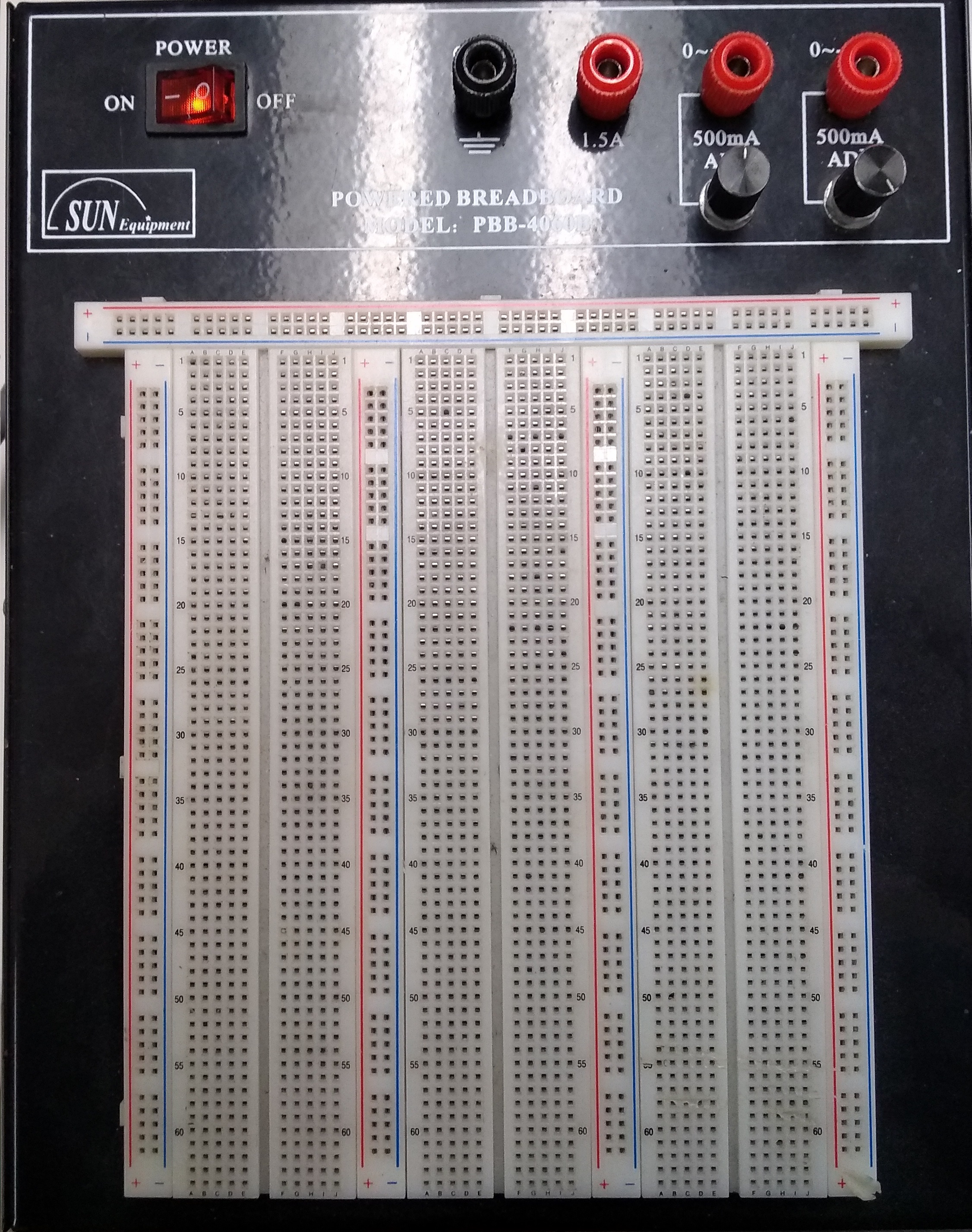
Breadboards are used for testing out circuit designs without the need to solder the components together. This means that each component can be reused afterwards and does not need to be cut. The breadboards in the Student Design Hub come with a built-in power source, so powering the circuit with an external power source (such as batteries) is not always necessary. The powered breadboards do not need to be powered by their built-in power source in order to work.
How the Breadboards are Connected
The following diagram shows how the breadboard is connected internally. Each yellow line can be thought of as a wire that connects to every hole it overlaps:
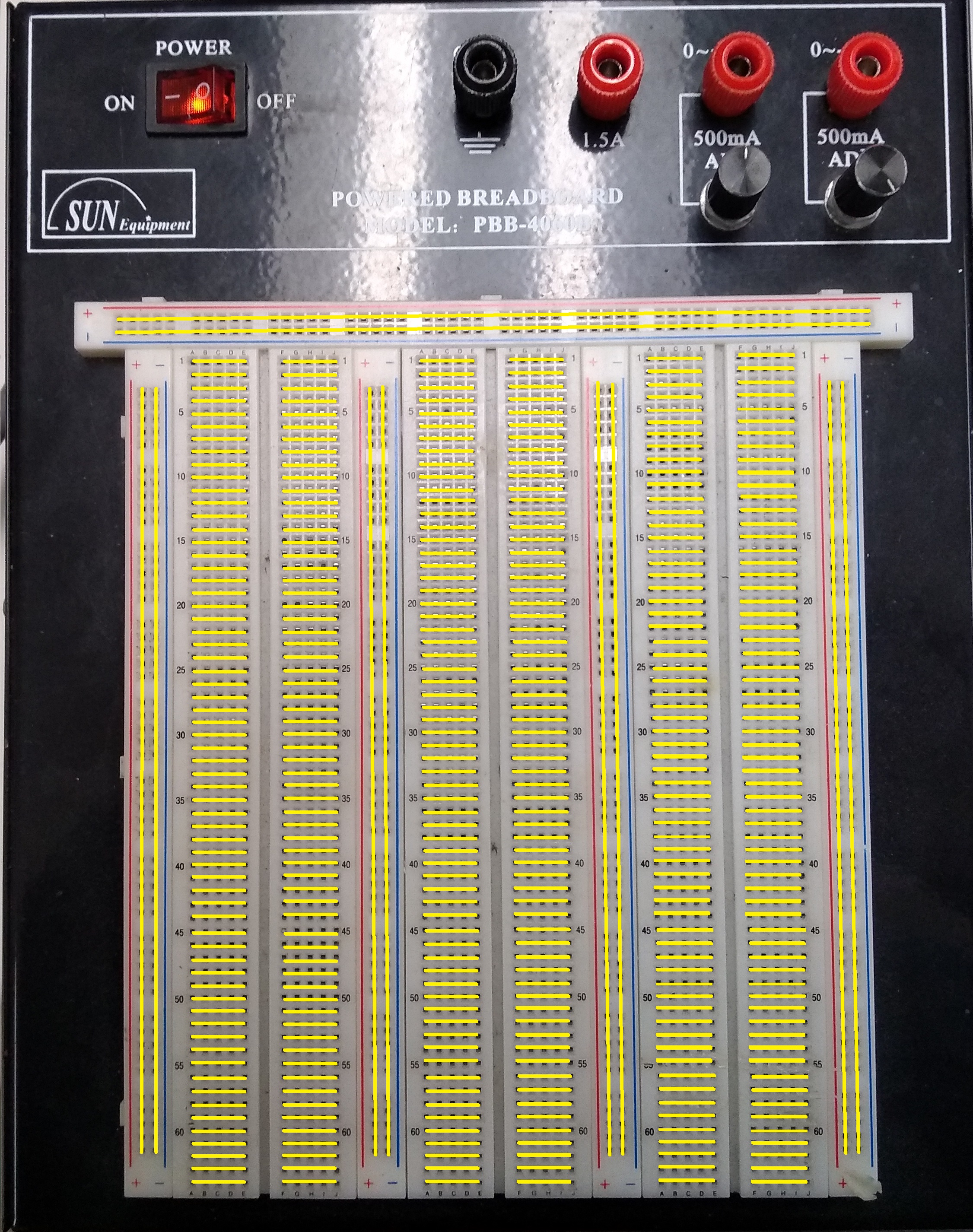
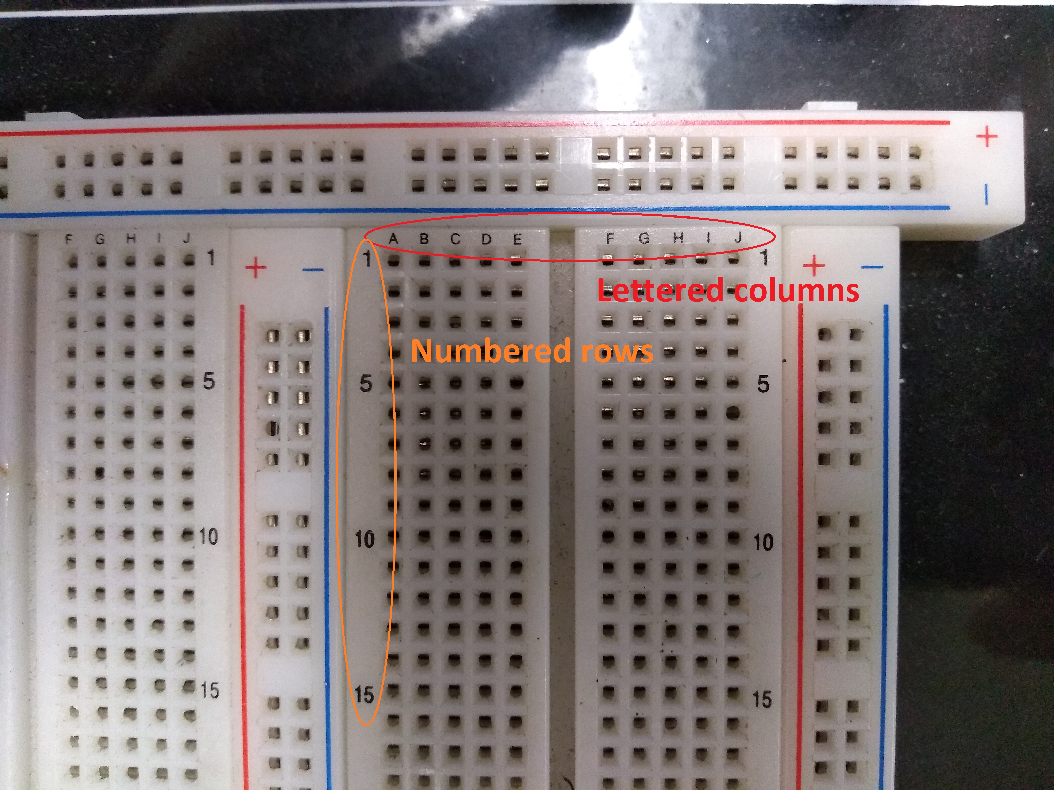
Each row on the breadboard is labelled numerically (1 to 64) and each column is labelled alphabetically (A to J).
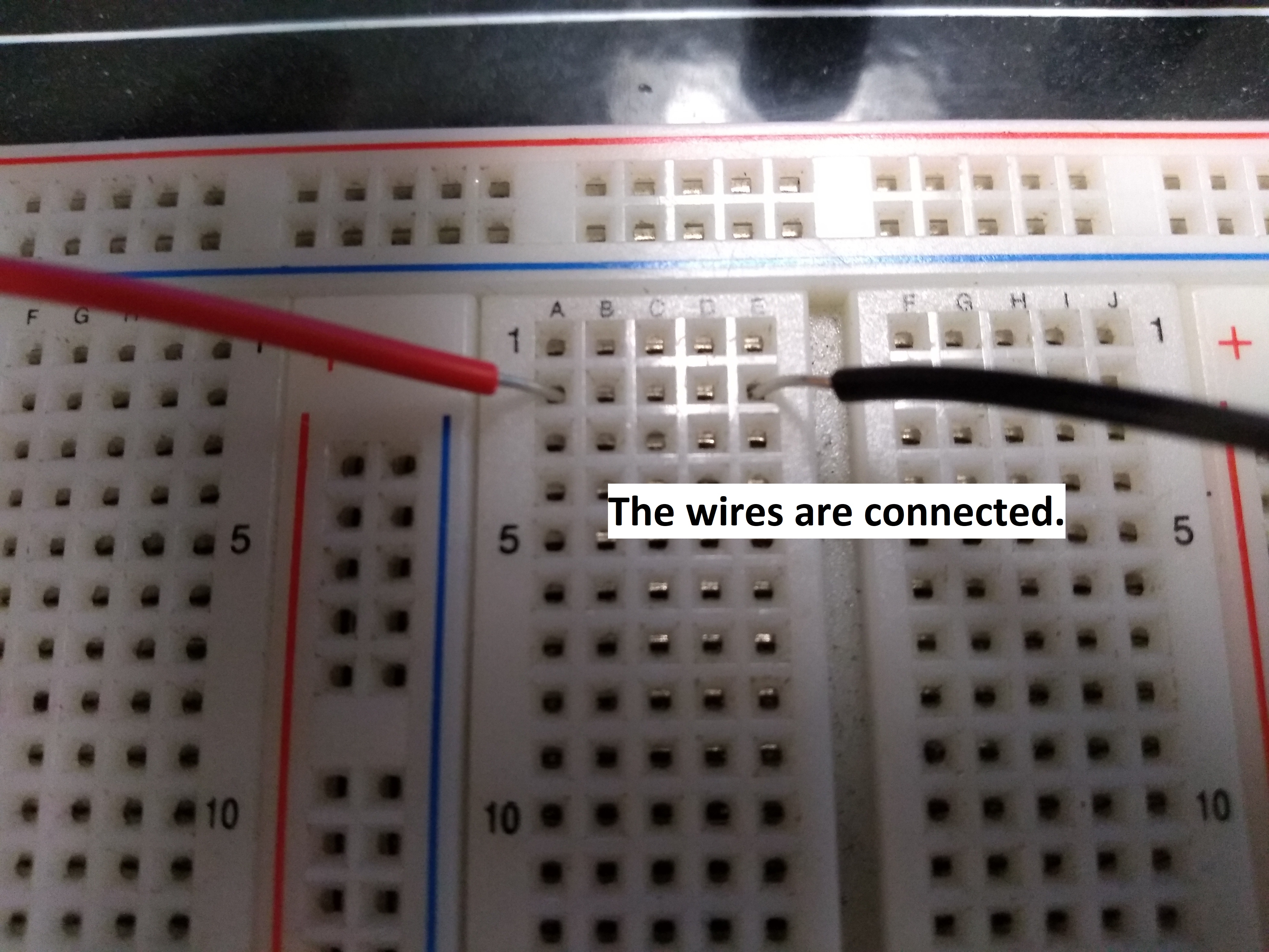
Putting two components in the same row (same number, different letters) connects them:
But putting them in the same column (different numbers, same letter) does not:
Powering the Breadboard
The breadboard can be powered using the power switch and knobs at the top of the device:
The red power switch on the left controls whether the knobs to the right receive any power.
The black knob labelled “COM” is the ground for the circuit.
The leftmost red knob labelled “+5V/1.5A” supplies 5V when the power switch is turned on.
The middle red knob labelled “0~+16V/500mA” supplies anywhere between 0V to +16V, which depends on the position of the black knob below it. The output of this red knob can be adjusted by simply turning the black knob.
The rightmost red knob labelled “0~-16V/500mA” supplies anywhere between 0V to -16V, which depends on the position of the black knob below it. The output of this red knob can be adjusted by simply turning the black knob.
The sides of the breadboard have red and blue lines labelled “+” and “-”. These lines show that all the holes along that line are connected together, and are meant to receive power from one of the red knobs (or the ground for the “-” end). These long connected lines are called rails.
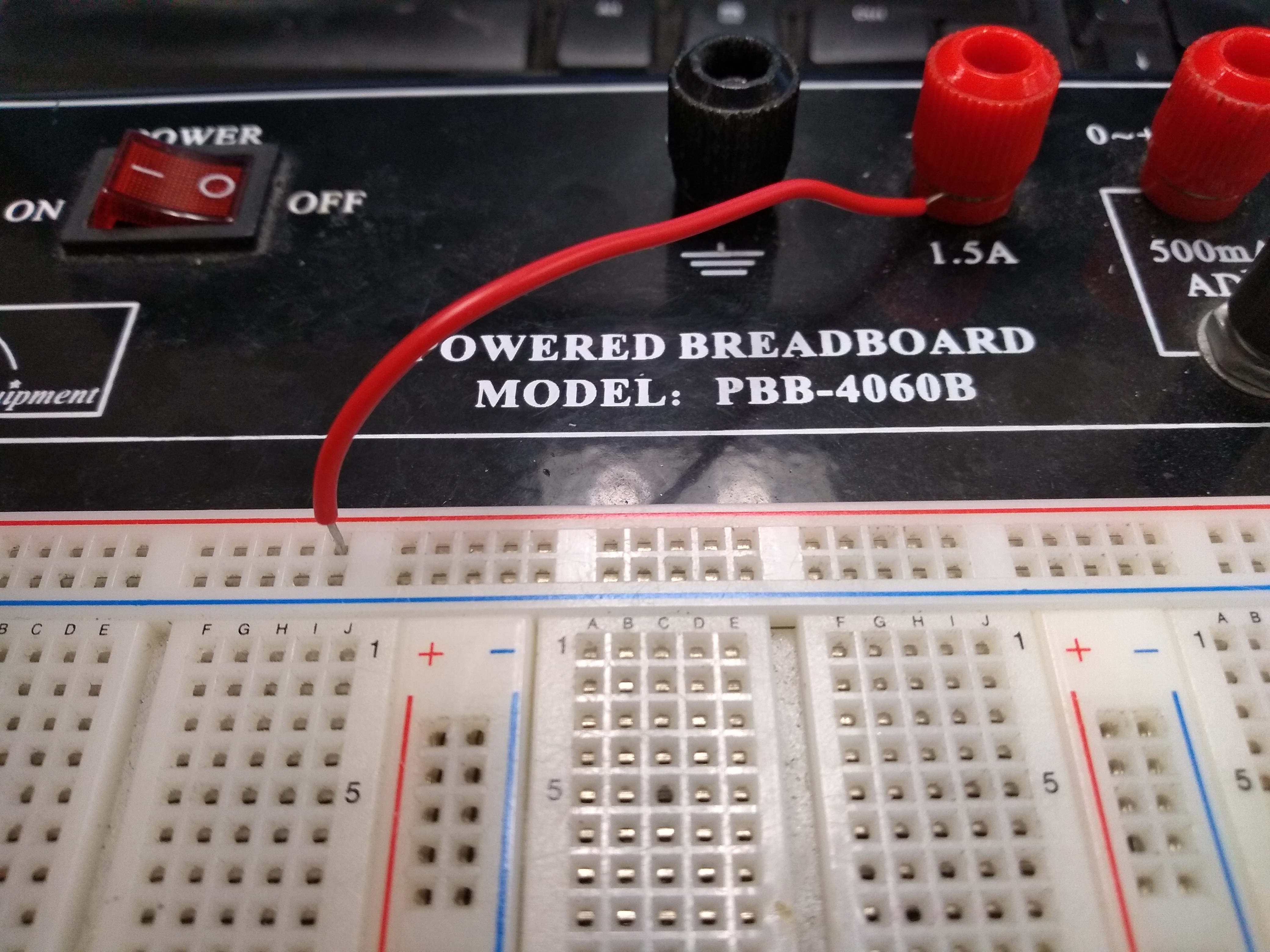
Simply turning on the power switch of the breadboard does not supply power to the power rails. A wire must run from one of the red knobs to the power rail. The ground rail must also be connected to the ground (COM) knob. The method for connecting a wire to one of these knobs is shown here:
This wire must then be inserted into a hole belonging to one of the power rails of the breadboard:
Note: Connected power to one rail does not connect power to all of them. Similarly, connecting ground to one (ground) rail does not ground all of them.
Example Circuit
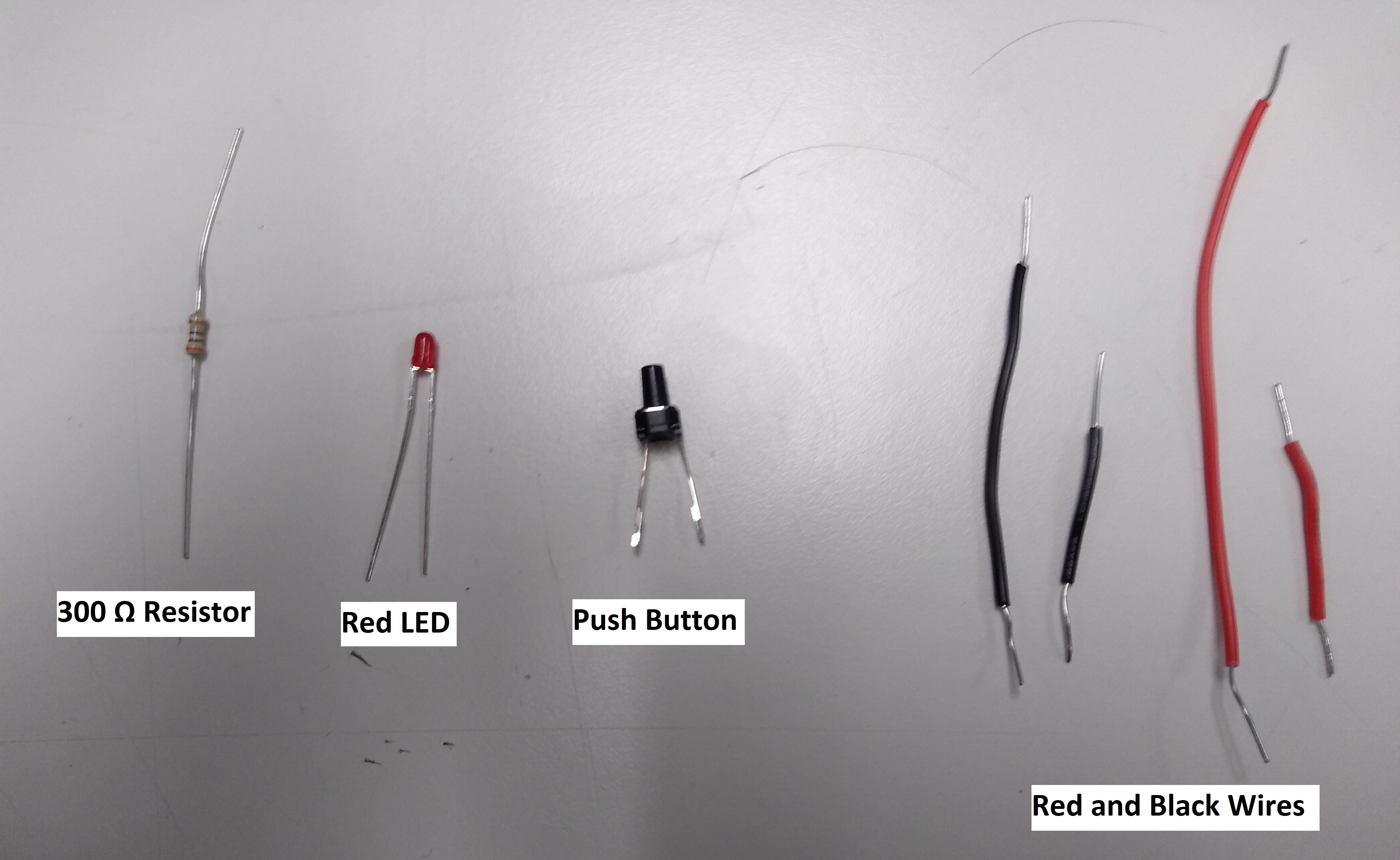
In this section, we will build a simple circuit involving a few wires, a 300 Ω resistor, a push button, and a Light-Emitting Diode (LED):
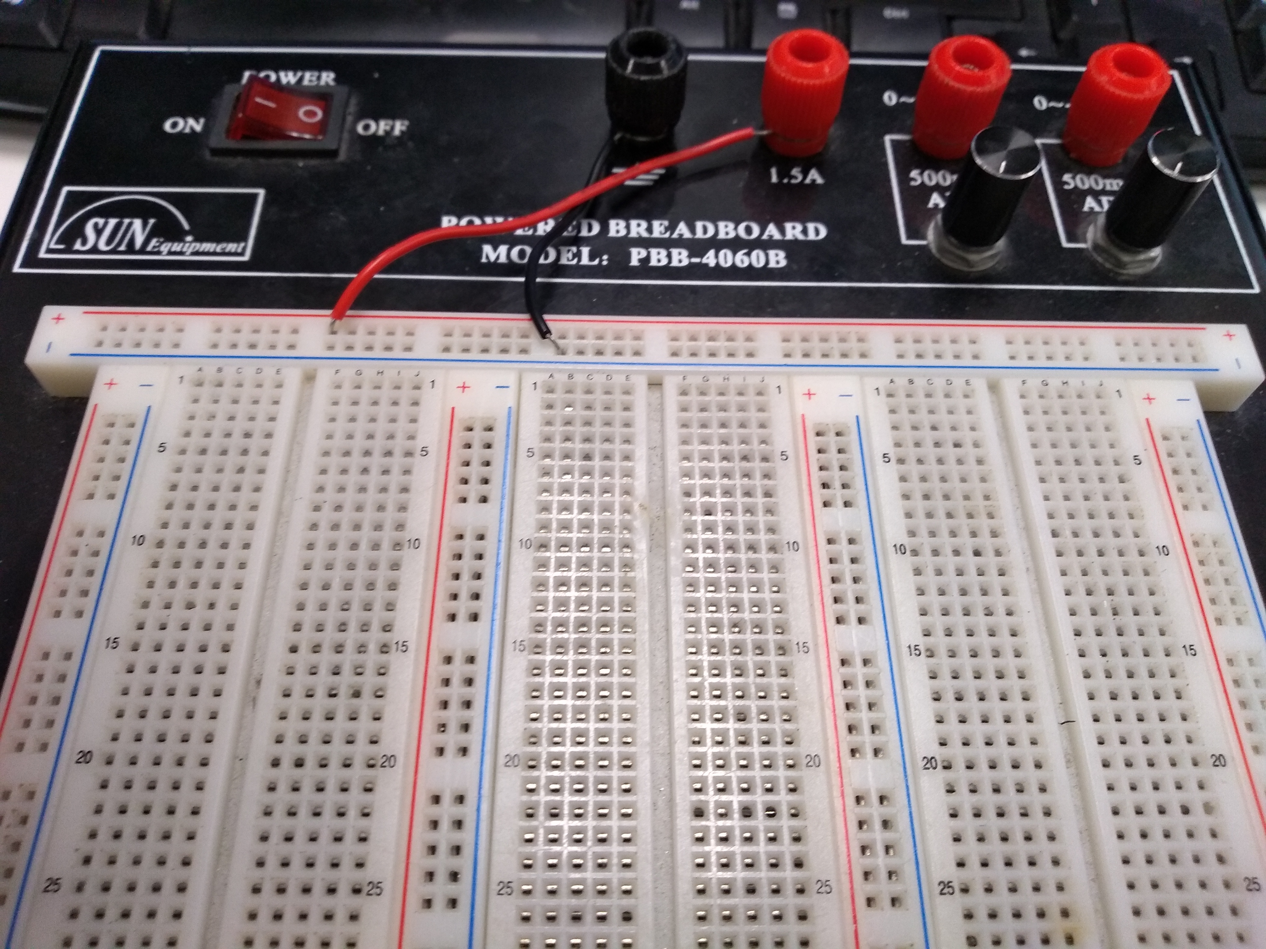
We will create a circuit that turns on the red LED whenever the button is pushed, and turns it off when the button is not pushed. The first step is to connect the power and ground knobs to one of the rails on the breadboard (the power switch on the breadboard should be in the “OFF” position until the circuit is complete):
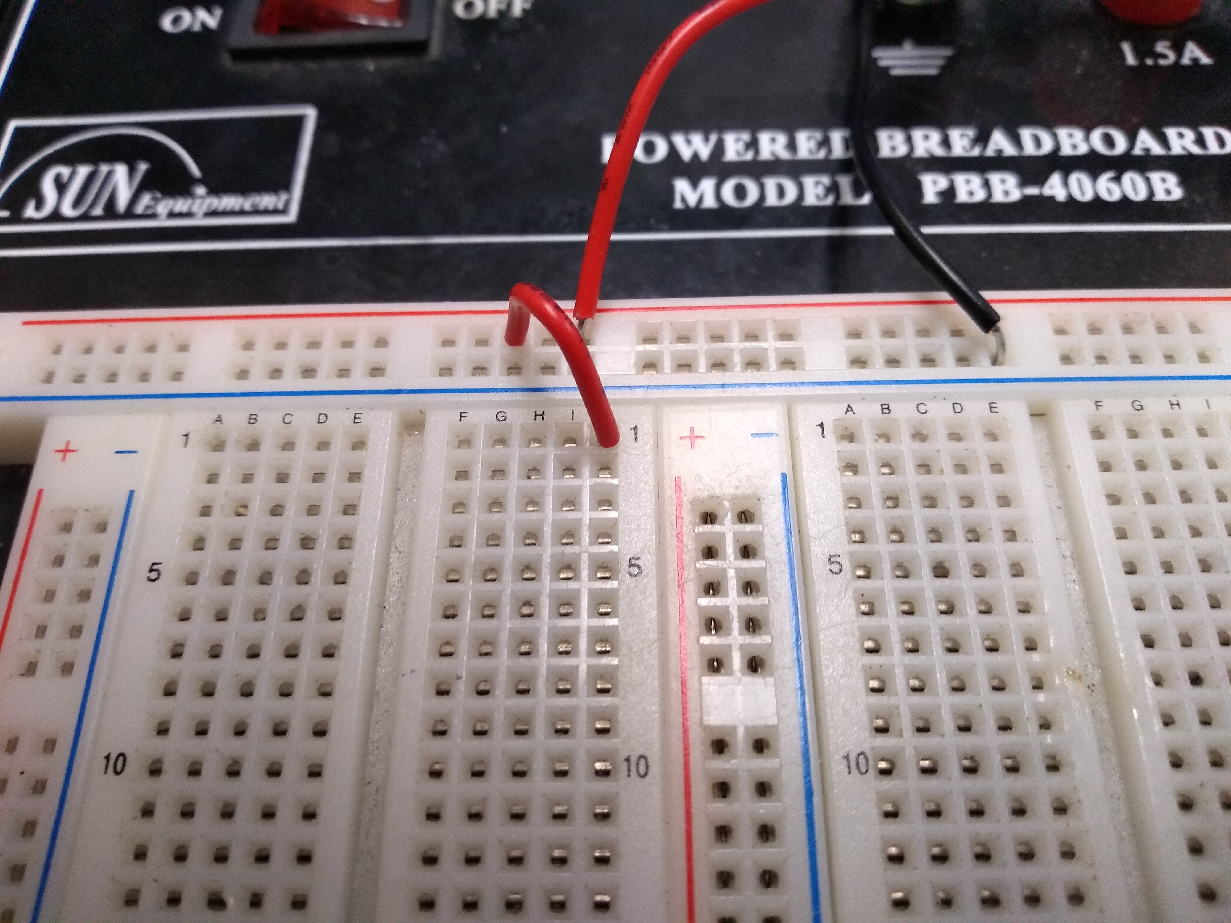
Now a smaller red wire must be connected to one of the rows on the breadboard:
Next, the push button must have one end connected to the short red wire and the other end placed across the gap, as shown here:
The resistor is then connected to the lead of the push button, with its other lead being connected to a new row:
Next is the LED. The LED is polar, meaning placing it in the wrong direction will prevent the circuit from working. The longer lead on the LED is the positive (+) lead, while the shorter lead is negative (-). The (conventional) current must flow from the positive lead to the negative lead, so the longest lead must be connected to the resistor:
Now take a short black wire and connect the LED lead to the negative rail:
The circuit is now complete. Turn the power switch on and try pressing the button. You should find that the LED turns on when the button is pressed, and turns off when it is not.
Example Circuit (Part 2)
You can also try out the adjustable knobs on the breadboard by making a few small changes to the circuit. Turn the power off and remove the push button from the circuit entirely. Connect the shorter red wire directly to the resistor lead and connect the longer red wire to the middle red knob. Your circuit should now look like this:
Now turn the power back on and try adjusting the black knob below the red knob that you hooked the wire up to. You should find that the brightness of the LED corresponds to the rotation of the knob:
End of tutorial.