Soldering SMD Components
Need: Solder paste, PCB stencil (optional), Tweezers/ Vacuum pen / pick and place machine
SMD components can be soldered in a variety of methods, from using pick and place machines, soldering pastes, to using soldering irons. The chosen method depends on the size/ package of your SMD component. The preferred solder used when soldering SMD components is in the form of a paste, called solder paste. The solder paste can be spread on the board using a stencil that is custom made for your PCB or by directly placing the solder paste using a pick and place machine.
SMD components can then be placed on the circuit board using two methods: using a tweezer or using the vacuum pen of a pick and place machine. All circuit boards with SMD components must be put through a reflow oven to allow the solder paste to solidify. The size limitation for PCB sizes usable with the pick and place is 4.75 X 10.75 inches while that of the reflow oven is 17 X 13 inches.
Placement using a Pick and Place Machine (without a stencil)
A pick and place machine is a robotic SMT assembly machine used to place surface mount devices on circuit boards. The alternative to using a pick and place machine would be to use a tweezer to place the surface mount component onto the board. Both methods will be explored and compared in this tutorial. It is always advised to use a stencil as it makes the PCB neater. Component placemnts can be more precise and consequently, there is a reduction in PCB faults like short circuits.
Using a pick and place
Step one: Turn on the pick and place using the red button next to the brand name and the computer system

Step two: Select digital viewer to open the camera

Step three: Turn on the compressor and click on the suction button 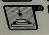 to turn on the vacuum pen. The compressor will function properly when the tank pressure is above 0 kpa/psi and the output pressure gauge is set to 100psi using the red air pressure regulator knob.

Step four: Position the solder paste tip to where you need the solder on and use the foot pedal under the table to allow the flow of the solder paste onto the circuit board. The vacuum head and the camera can also be moved. Move all the elements until they are in a suitable position for your assembly. Use the green buttons to move the vacuum tip up and down.

Step five: Read the How to use a Reflow Oven tutorial with a focus on step 4. Apply solder paste on the pins using the foot pedal, then heat the board in the reflow oven until it reaches a shiny silver finish, then clean the extra flux on the pads to ensure there are no short circuits. Now use the vacuum pen to pick up components and place them onto the board.

Step six: Reflow using a reflow oven or hot air gun.
Step seven: Remove excess flux using isopropyl alcohol and cotton swabs or lint free wipes
Using a Stencil with a Pick and Place / Tweezer
Step one: Apply Solder Paste
Apply solder paste to the circuit board using a stencil. Alternatively, if a stencil is not being used, use the:ref:Using a pick and place tutorial. Place the stencil on the circuit board, secure it with tape, and spread the solder paste onto the stencil.

Step two: Placement of SMD Component
Using a Tweezer
Pick the SMD component using a tweezer and slightly press onto board to ensure good contact with board before reflow Reflow using a reflow oven or hot air gun. Remove excess flux using isopropyl alcohol and cotton swabs or lint free wipes
Placement using a Pick and Place Machine (with a stencil)
Turn on the system
Select digital viewer to open the camera
Turn on the compressor and click on the suction button to turn on the vacuum pen
Pick up the component with the vacuum pen and place it on the board. Press onto board to ensure good contact with board before reflow, which should also switch off the vacuum.
Reflow using a reflow oven or hot air gun.
Remove excess flux using isopropyl alcohol and cotton swabs or lint free wipes
Step three: Reflow Soldering
What is reflow soldering?
Reflow soldering is the process of heating up a solder paste to join two metals. A successful reflow soldering process needs the right temperature at the reflow zone of the process. Different solder pastes are made from different alloys of metals as such all have different reflow temperatures - this is encapsulated into a standard reflow profile.
Solder Paste
The shelf life of solder paste is between 6-9 months and should be stored in between 1 - 6 degrees celsius. Solder pastes will come with recommended reflow profiles. It is up to you, to twitch or use the profile as it is.
The standard reflow profile has four zones:
Preheat zone: preheating to activate the flux
Soak zone: equalize the temperature of all components to the same temperature
Reflow zone: temperature rises above melting point to complete reflow
Cooling zone: temperature reduction to allowing cooling of the board

The recommended solder profile for a Chipquik solder paste with alloy composition Sn42, Bi57.6, and Ag0.4 is as seen below. An Important thing to note is the maximum temperature of the reflow zone, which is 165 degrees celsius.

How to use a Reflow Oven
Step one: Turn on oven using the red switch on the side and then pressing this button  on the front.
Step two: Program selection is dependent upon component density, PCB type and size. Since it is quite impossible to determine the right program to select. It is recommended to choose a lower rather than high profile to prevent damages to the PCB. Select a program based on the recommended solder profile of your solder paste. The max temperature from above is 165 degrees. So the reflow temp should not exceed 165 degrees, but let’s select program 16 with a reflow temp of 170 degrees. Keep in mind that this is an old reflow oven, so it may underperform.
Select a program by selecting  , use the
  buttons to navigate between the programs shown on the LCD screen
 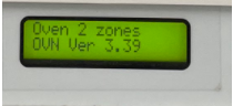 . When the right program is shown on the screen, press
  to select it. If you want to manually create a program, use this button
  .
.

Using the program number 16 was perfect for a Chipquik solder paste with alloy composition Sn42, Bi57.6, and Ag0.4 and the board used.
Step 3: Place your PCB on the drawer and wait for the oven to heat up. When it reaches the right temperature, an acoustical sound will play. Use the drawer button  to move the drawer into the oven.

Step 4: Wait for the reflow process to finish. When the reflow process reaches the end, it will automatically bring out the drawer to its initial position. If you would like to bring out the drawer before the process is finished, use the drawer out button  .
.
