Computer-Aided Manufacturing Using Fusion360
1. This tutorial assumes that you already have created a part that you would like to machine. Remember, you need to design your parts around the machining tools you have available. Now that your part is ready, you can start generating tool paths! To start setting up your tool paths navigate to the manufacturing tool space. Then Select Set-Up
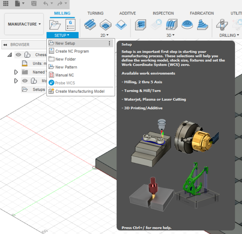
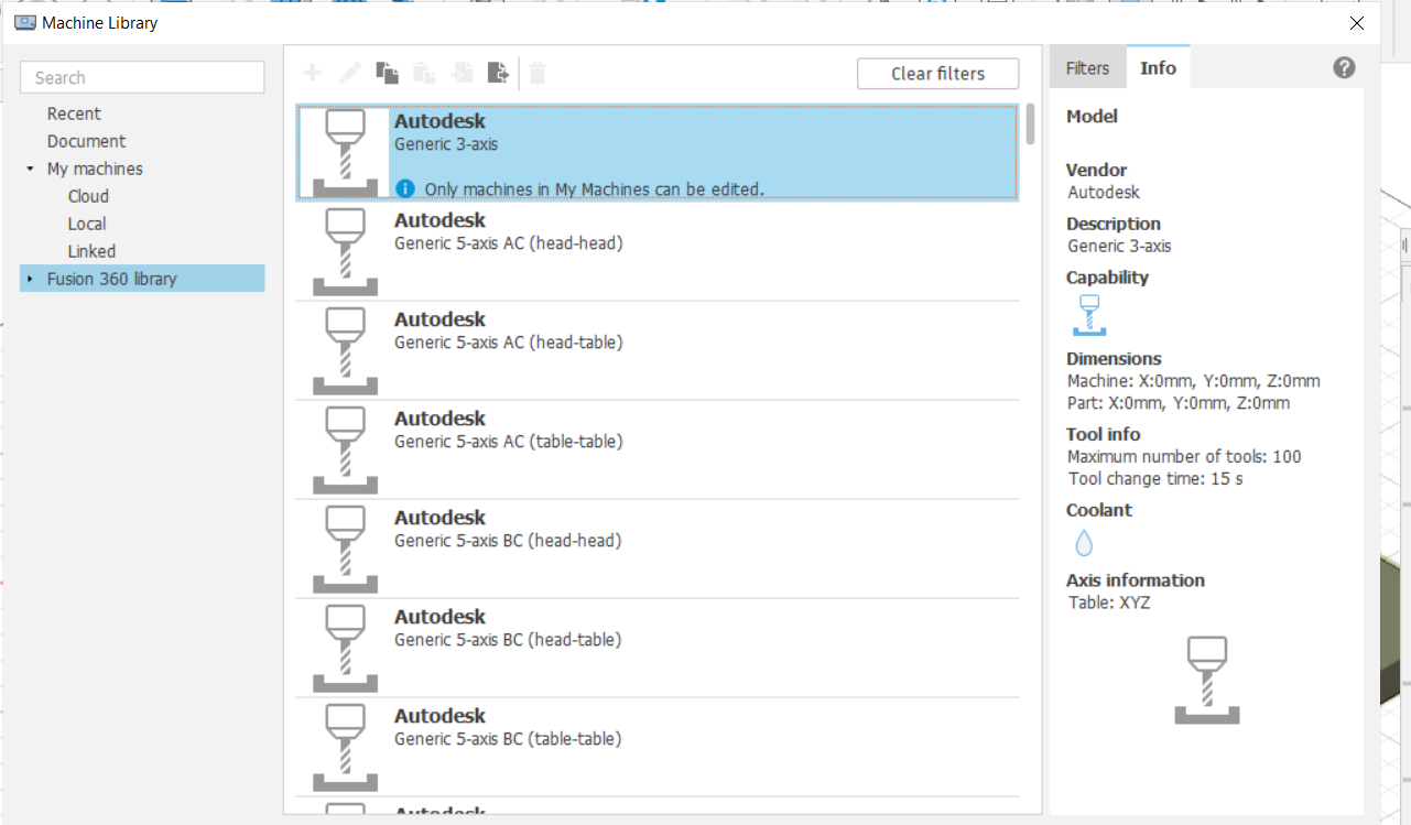
Selecting new setup will generate a smaller menu. Near the top you’ll see “Machine”. Click this option to open the machines menu.
The X-Carve is a “Generic Three Axis Router”.
The MakerDreams EVO-One is a “Generic 3-Axis Mill”
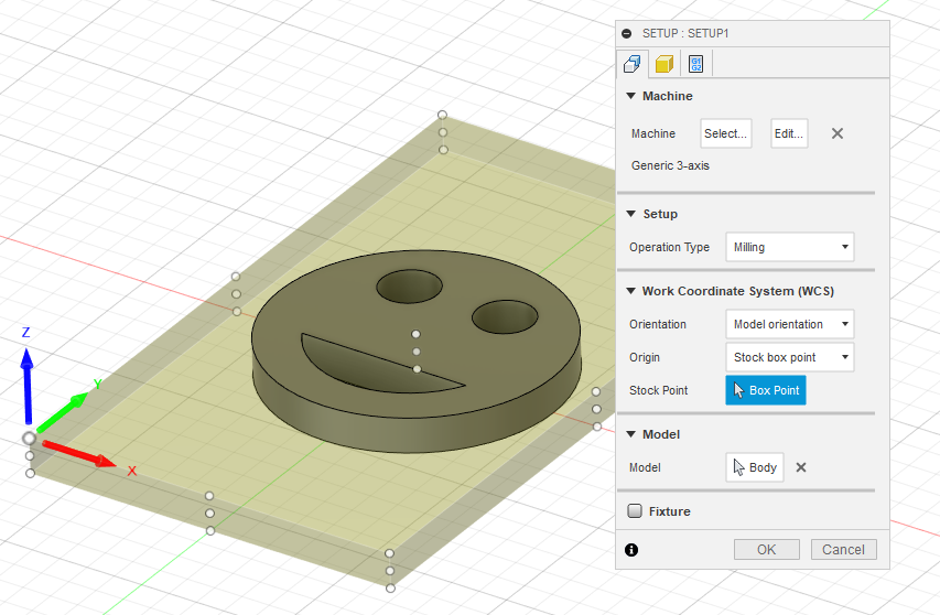
3. After you’ve selected your machine, you’ll need to identify your origin. The origin should be on the top surface of your stock. Often the bottom left corner on the top surface of the part is a good option to select. On your menu select origin -> selected point. Then select the point on your model you’d like for the machine to start from. NOTE: do not pick a point on the bottom surface of the stock. In most CNC operations the spindle will default back to home on a stop or at the end of a cut. It will take the most direct path. Selecting the bottom face of your stock may cause the bit to drag through your material.
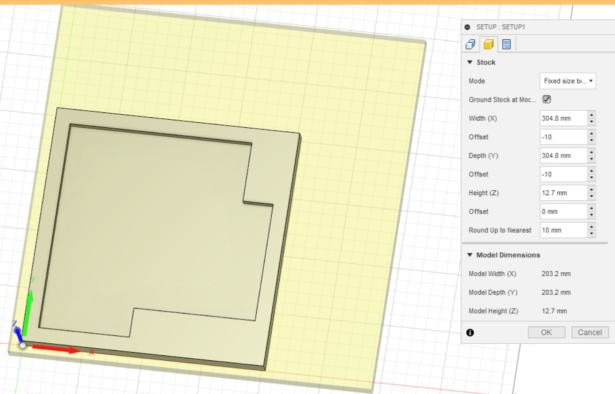
4. Now that you’ve selected your origin, you need to define your stock. This will let Fusion know how big the stock material you’re using is relative to your part. This tutorial will show two examples (a depth cut on a standard piece of stock, and a profile cut with tabs). For this tutorial we’ll be using a piece of scrap stock with the following dimensions (130mm x 225mm x 12mm). Make sure to accurately measure your stock with calipers before you enter these measurements. When choosing your stock it’s important to remember that each machine has a maximum bed size, and you need to account for material hold downs as well. It’s usually a good idea to define the stock with a boundary to account for how it will be secured to the bed (if using clamps for example).
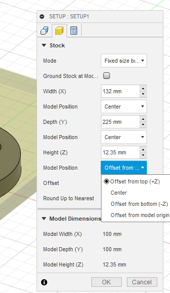
Select Fixed Size Box to define your stock by entering your measured dimensions.
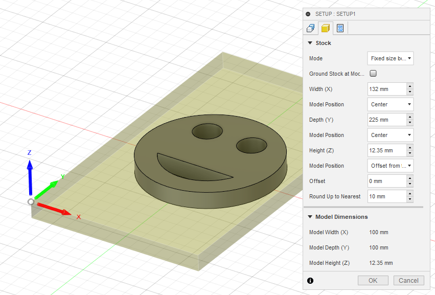
If you are only making a single part from the stock and aren’t worried about wastage, you can center the part in the stock. One thing to remember is that when setting your z-axis offset you should select “Offset from top”. Selecting “Center” under model position for the X and Y axis will set the cut in the stocks center.
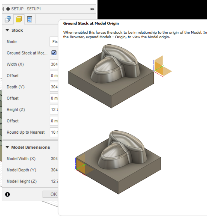
You also have the option to ground the stock at the origin. This will force the stock to move relative to your defined origin. This can be desirable if you plan to use the remaining material for other projects.
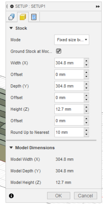
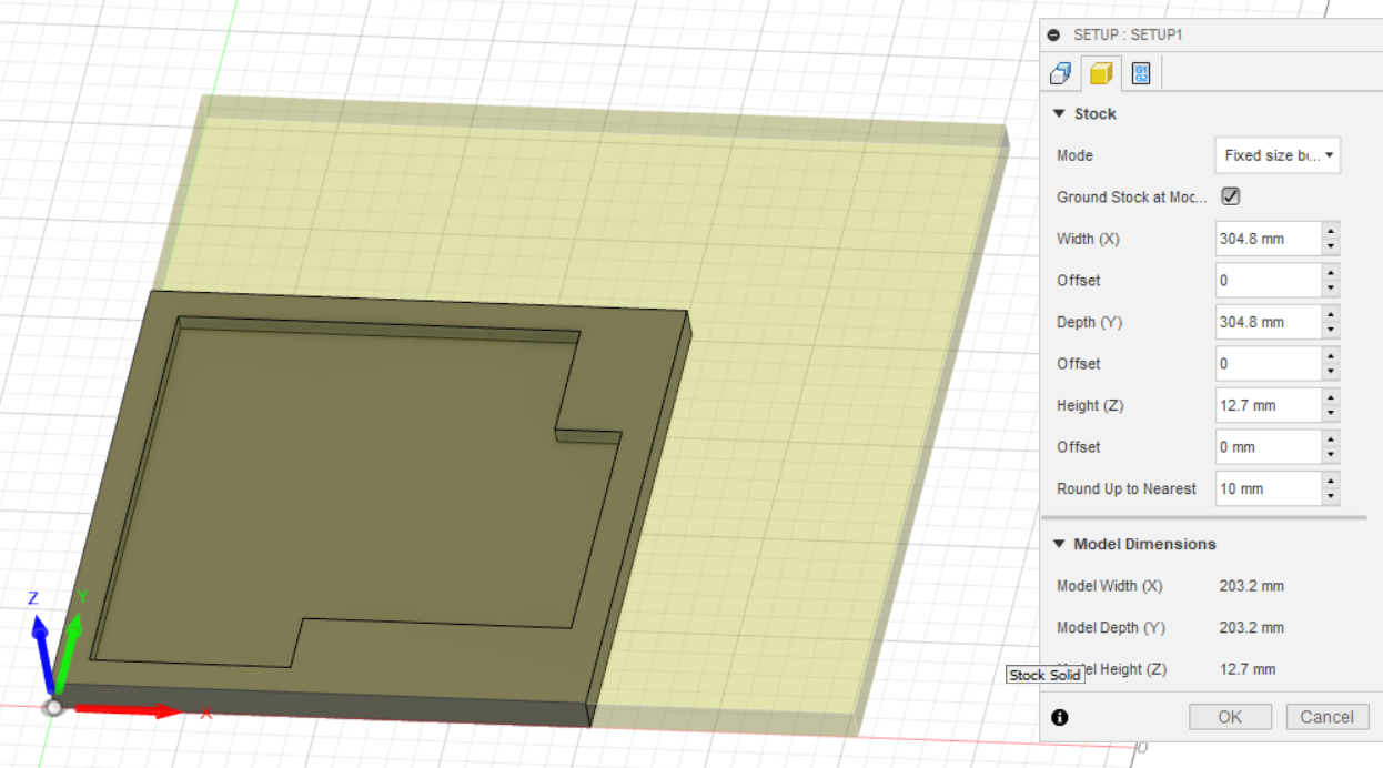
One thing to consider is that your material may not be perfectly square, you may want to offset the part so it is partially inside the material stock but also minimizes wastage. You also need to consider clamps and hold downs, ensure you leave enough of a boundary based on the clamping you plan to use.
The next step is to define our cutting tool. Your cutting tool is the bit you’re going to use in the spindle or router to complete the operation. The types of bits available vary, and their purposes also vary. If you’re removing a lot of material, larger bits are desirable, while fine details and different geometries can be achieved with different finishing bits. To select the bit you’ll use for this operation select “Manage” at the top of the screen, and then press “Tool Library”.

In the tool menu you’ll be able to select from all of the tools available in the Fusion 360 tool library. You can also import tools / or add customer tools based on what you have available. For example, Bantam tools has an entire tool library that can be imported into Fusion 360.
Before we set up a custom tool to match what we have available in our lab, we’re going to review the tool library functions. On the right-hand side of your screen you’ll see the tool filter menu. This will allow you to filter all the tools available in your library. For this example operation we’re going to be using a 1/16” End Mill. To find the end mills available we select “Milling” as the Operation, and “Flat End Mill” as the tool.
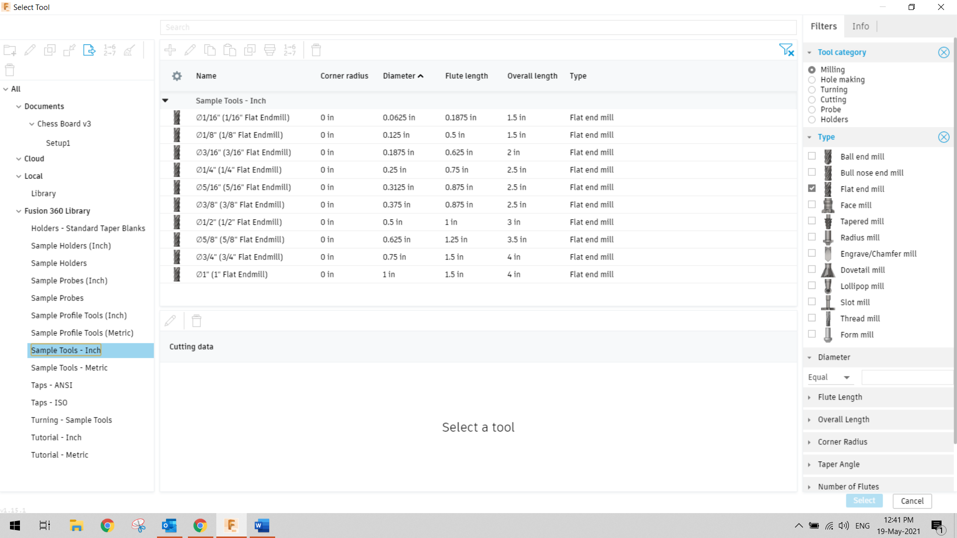
You may notice that nothing populates in your menu. To show the available tools that fit your filter, click Sample Tools on the Left Hand Menu. This will bring up all tools that match your filter. Select the 1/16” Flat End Mill from the menu.
Now that you’ve selected a tool Fusion 360 will try to suggest some cutting parameters. These parameters will change based on what you select on the lower menu. Let’s assume for the purpose of this example we were going to make a pocket cut out of ABS. There are a variety of plastic cutting options already in Fusion 360. These will get you very close approximate cutting parameters for the sample bit you select.
NOTE: The X-Carve CNC is not set up for variable speed control. It must be controlled through the manual dial on the router body. To see a speed reference document, add hyperclick here.
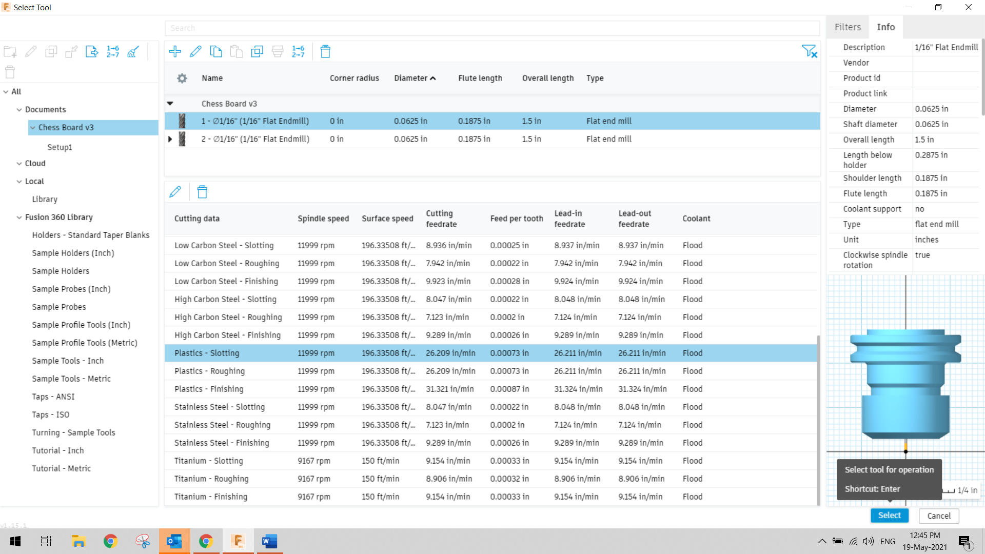
Note: You can’t simply select any sample tool and move on. The tool parameters that you select / set here MUST match the actual bit you’re going to use in the cutting operation. If the bit is a different length, diameter, or if the flute length (which means cutting edge) do not match the bit in the machine will have issue cutting your stock and may ruin your material.
For Example If I set up a tool path with a 1/8” bit, but then leave a 1/16” bit in the machine and try to complete my cutting operations. The machine will assume that the bit is 1/8” wide and will travel along the center point of the bit. This means you will be leaving material behind that your machine believes you removed as it’s not compensating for the difference between the bit diameters (i.e. a 1/8” removes twice as much material as a 1/16” bit, so there will be a 1/16” slot cut along what is supposed to be a 1/8” path).
8. Verify your bit This step is straight forward, head over to your toolbox and take measurements of the bit you plan to use. In some cases, the container may include some of these details. If the bit isn’t available in your tool library you’ll need to create a custom tool. It’s recommended that any bit that you use in this lab be set up as a custom tool to ensure you do not waste any material. Don’t worry! You only need to set up each bit once
Start by creating a custom tool library in the Tool Library tool that we have open. Right click on Local and select “Crete New Library”. Then name the library after the machine you’re using. In the screen shot below we set up the “Evo-One”.
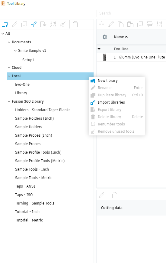
Now that you’ve selected a library, click on it. This will enable you to add a tool by clicking on the Plus symbol at the top of the window.
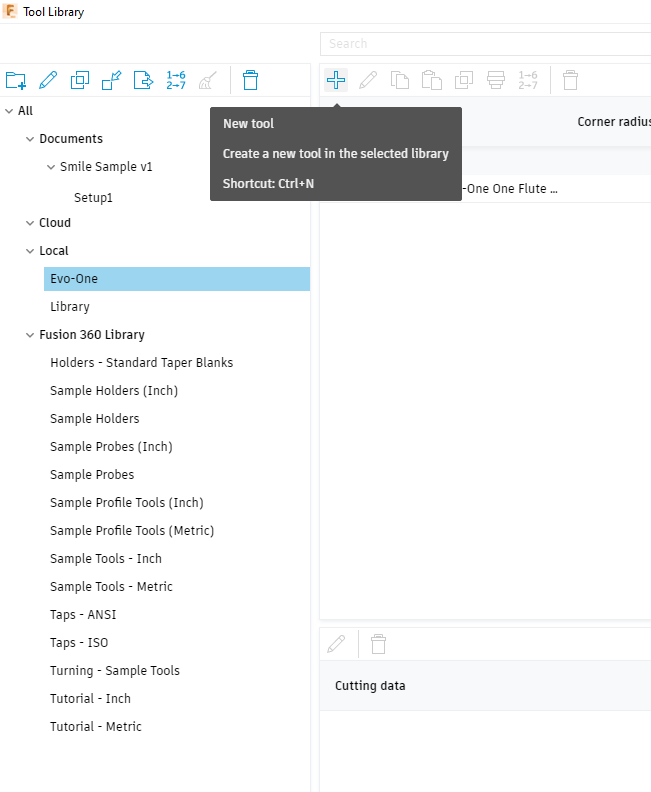
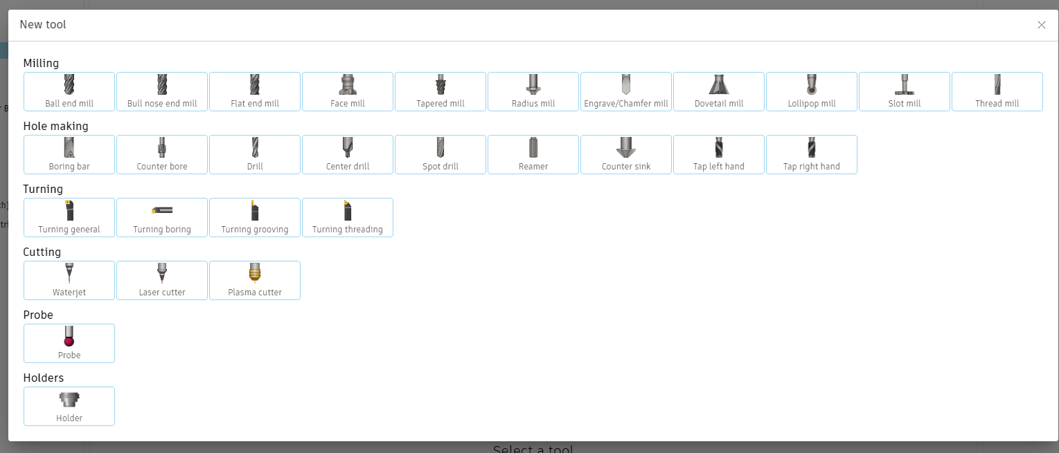
To start adding the bit, select the type of bit being used. In this case we’re using a “Flat End Mill”. This will open the Tool Creating Menu.
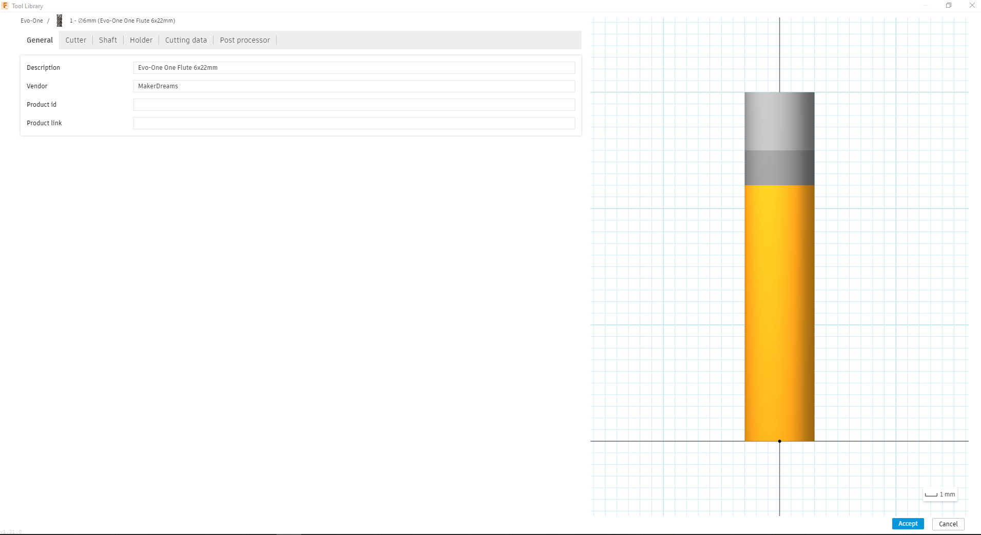
The first screen will be called General. This is where you name the bit and the Bit Manufacturer (as well as the bit product number if available).
Next you’ll want to Open the “Cutter” Tab. This tab will be where you define the bit parameters. Measure the bit and enter the parameters. Some of the parameters will be listed on the bit holder, but you’ll need to take some measurements as well. If you click each box, they will visually show you what dimension they need.
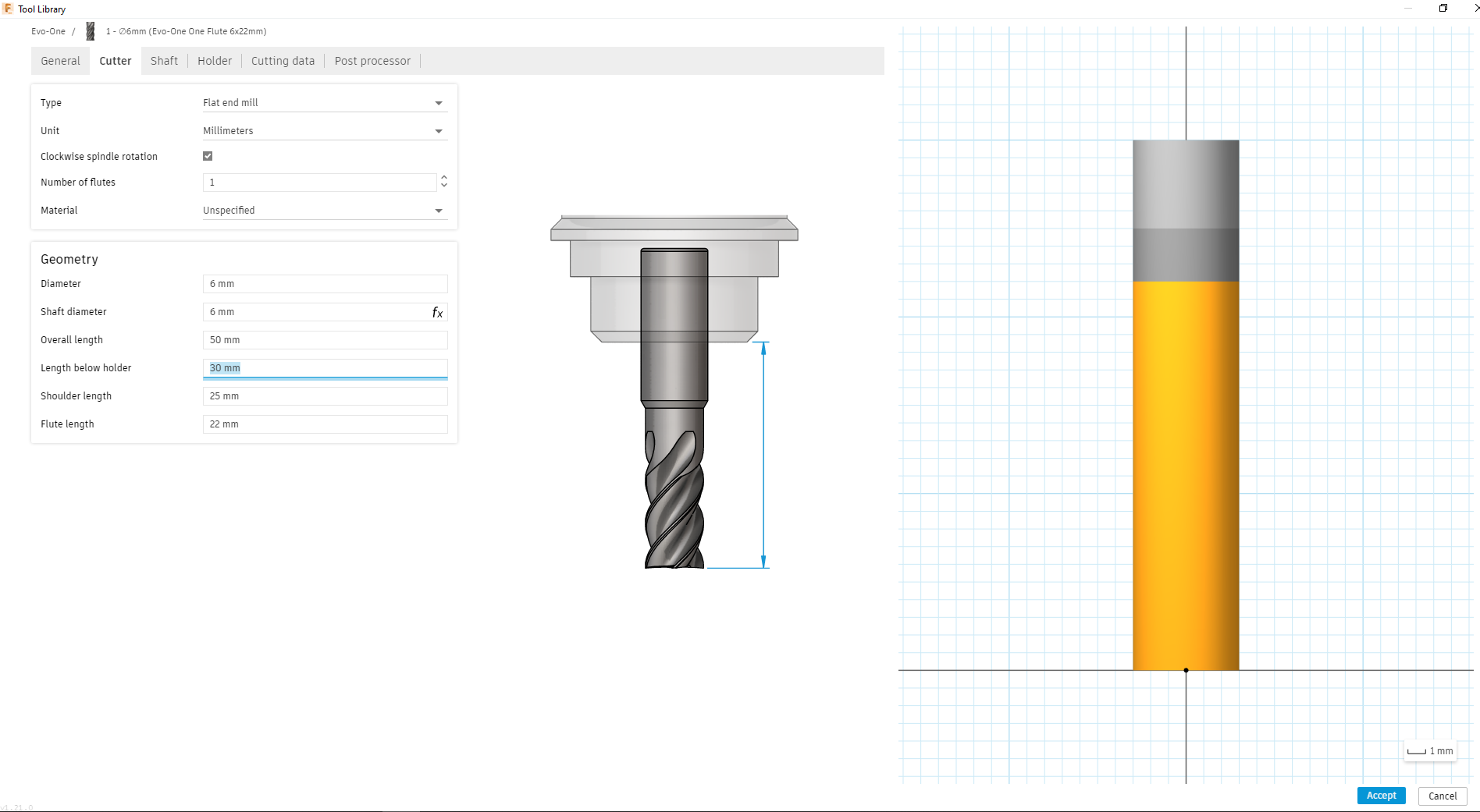
NOTE: not all bits have shoulders. If your bit doesn’t have a shoulder, indicate that the shoulder is 2-3mm past the end of the cutting edge (i.e. the flute).
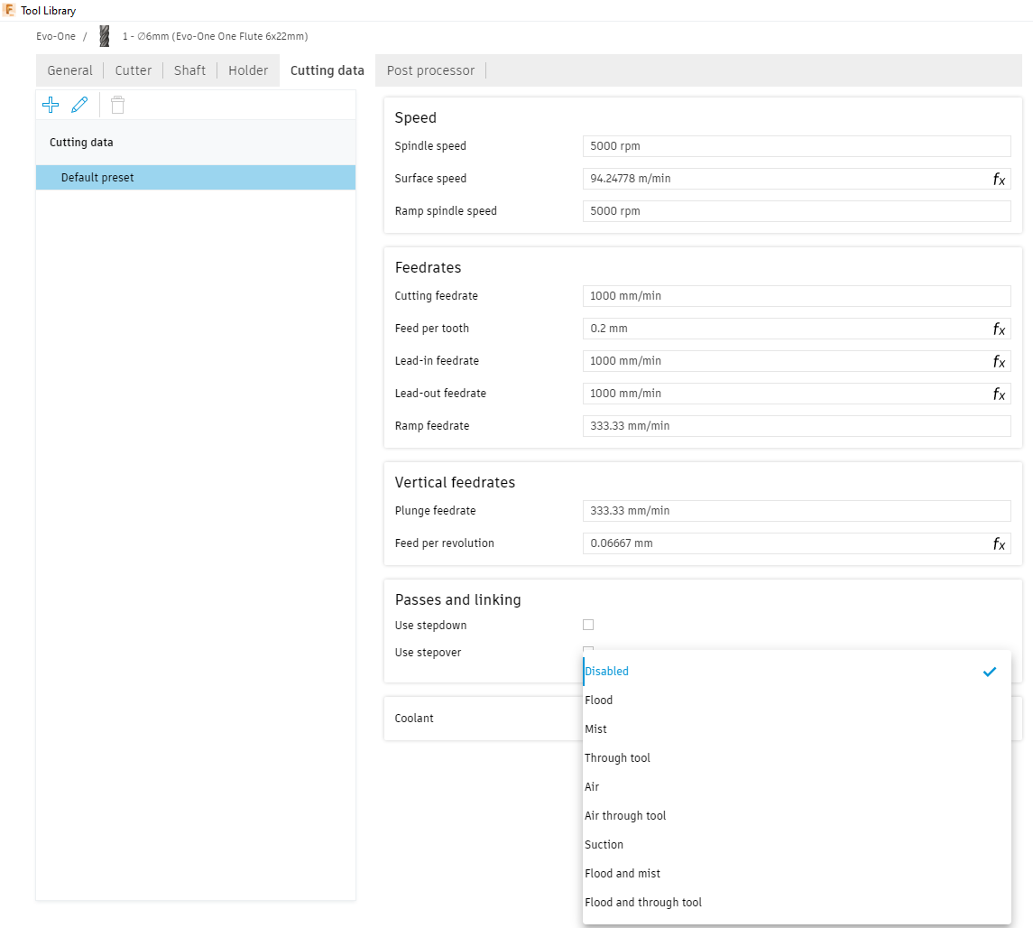
Next go to the Cutting Data Tab. This is where you can set the default cutting details for the bit. You can set all of these parameters before you start cutting in the toolpath menus as well, so don’t worry about them too much. The main thing to do here is go to “Coolant” and select “disabled” as neither machine is set up for coolant.
Now that your bit has been set up you’re good to start creating your toolpaths!
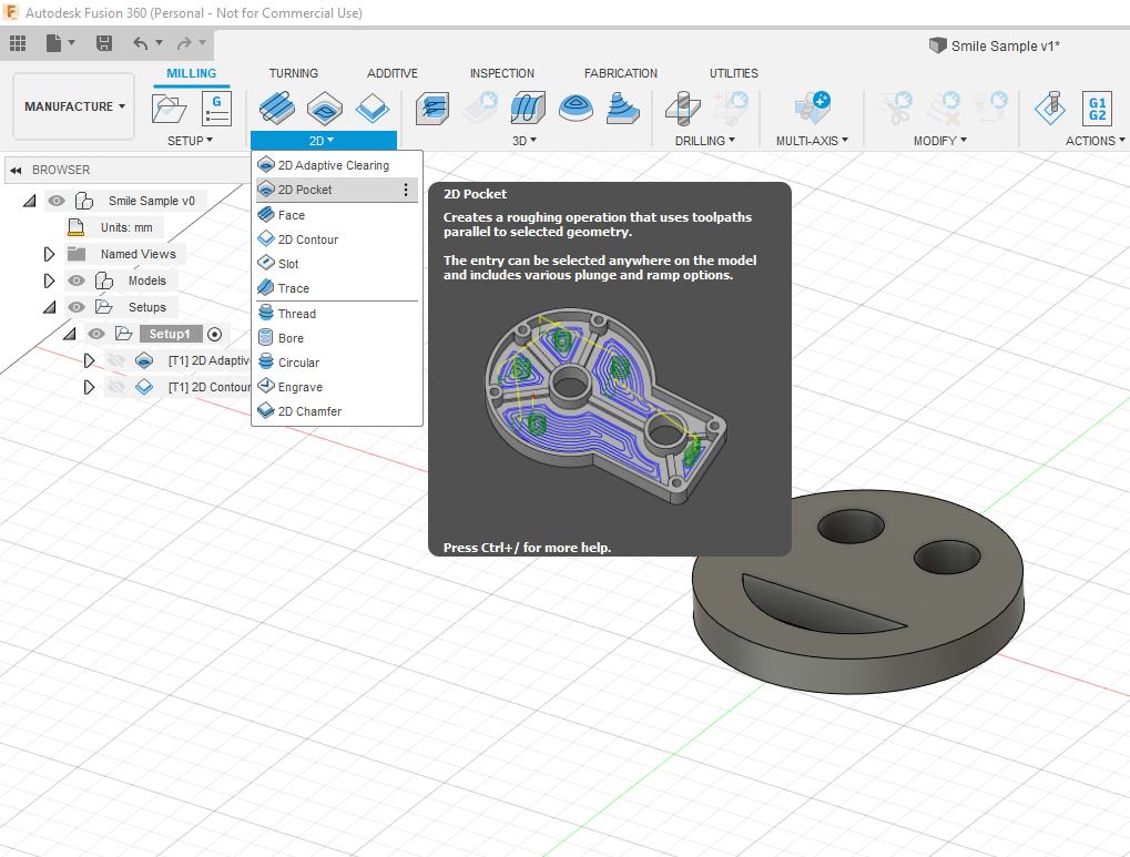
For this part we’re going to do two operations as mentioned above. We’ll start with the Adaptive 2D Pocket. Go to the “2D” menu at the top of the screen and select “2D Pocket”.
Under the tool menu, click the select option to open the tool menu. Then navigate to the tool you created! This will pull in all the tool’s default parameters. Before we go any further we need to set the cutting properties. When you select a generic tool, the menu gives you some default cutting properties based on the materials you may want tot cut, however this doesn’t happen for a custom tool. To make sure your surface finishes are the best possible it’s best to do some research on cutting parameters for your material. A great resource for this can be found here. hyperlink
Note: THE X-Carve is only recommended for cutting plastics and wood. For metals like brass and aluminum you will need to use the Evo-One.
In the example above, we’re using MDF board so the cutting parameters aren’t hugely important. However, let’s pretend we’re using ABS as the material for this example. We could then got to the bantam tool website and follow their suggested cutting parameter based on the bit we set up. Hyperlink
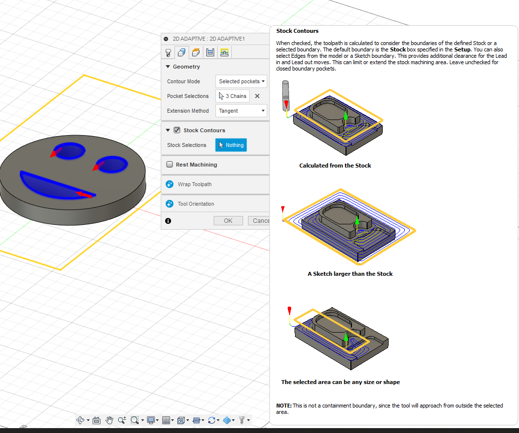
Now that we’ve tweaked our cutting parameters, we’re going to look through the toolpath settings. Under “Geometry” ensure you select “Stock Contours” this will ensure that the toolpaths will consider the boundaries of your stock.
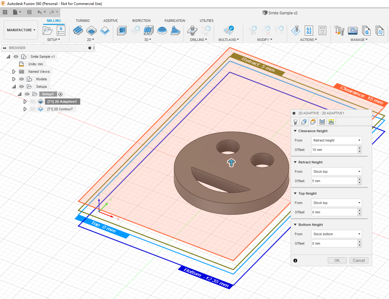
Next move to the “Heights” menu. This menu is incredibly important as it tells the toolpath where each operational plane is.
Clearance: How far up the bit needs to move to ensure it doesn’t collide with anything on the bed
Retract: how far up the bit needs to move to clear the surface of the stock
Top: where the top surface of the stock is
Bottom: where the bottom surface of the stock is
At each dropdown you need to define a distance from the reference plane. For Bottom Height, ensure that you select “Stock Bottom” and make the offset 0mm.
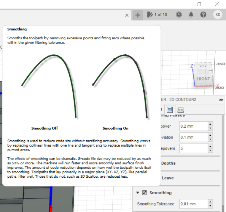
Under the “Passes” menu there are several important selections to make. At the bottom of the menu select smoothing and feed optimization. Smoothing will reduce the complexity of your G-Code resulting in better run time optimization (and lower likelihood for errors). Feed optimization will adjust the speed of the equipment as it approaches corners.
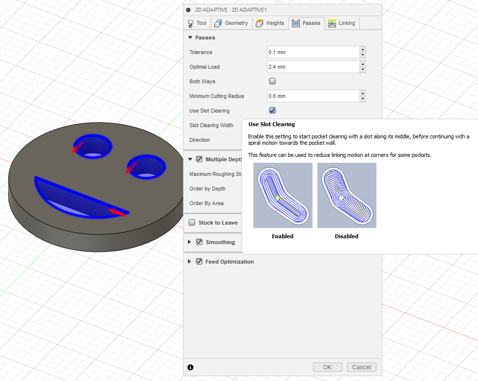
Next under “Passes” click “Use Slot Clearing” Slot Clearing reduces linking complexity at pocket corners and results in more optimized machine code.
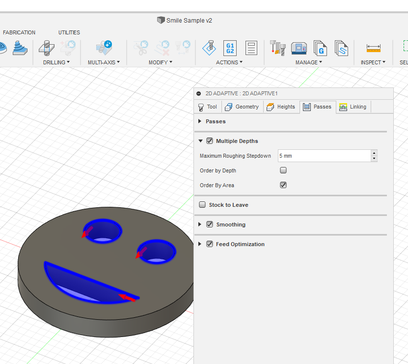
Next under “Multiple Depths” set the “maximum roughing stepdown”. This is the maximum the machine will plunge down between each cut. This can be any depth, consider your material. It’s better to take additional time to cut your part over multiple passes, than one quick cut. Multiple shallower cuts ensure a better surface finish. Under this section you can select the following as well:
Order by Depth: This will do all cuts at the first depth, then repeat the pattern to the next depth. Imagine you’re cutting two holes and the part is 12mm thick while doing 6mm deep cuts. Order by depth will cut 6mm in both holes, and then start over to do the next 6mm at the first hole again.
Order by Area: The entire cut will be complete in one location before moving to the next. In the two hole example above, it would finish hole one before moving to hole two
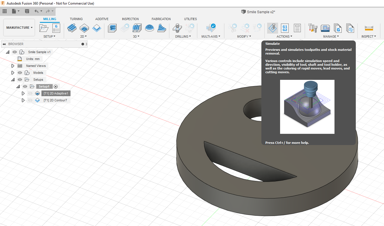
You can now click OK! This will be all the parameters required to do a pocket cut. To do so, go to the top menu and select “Simulate” under “actions
You can now watch how the tool will behave! Press play to watch how the tool will complete the operations you just programed. The yellow line shows how the machine will move in the Z axis, and the green represents the stock that you defined. You should see the material is fully removed from the pockets “through” the stock over multiple passes.
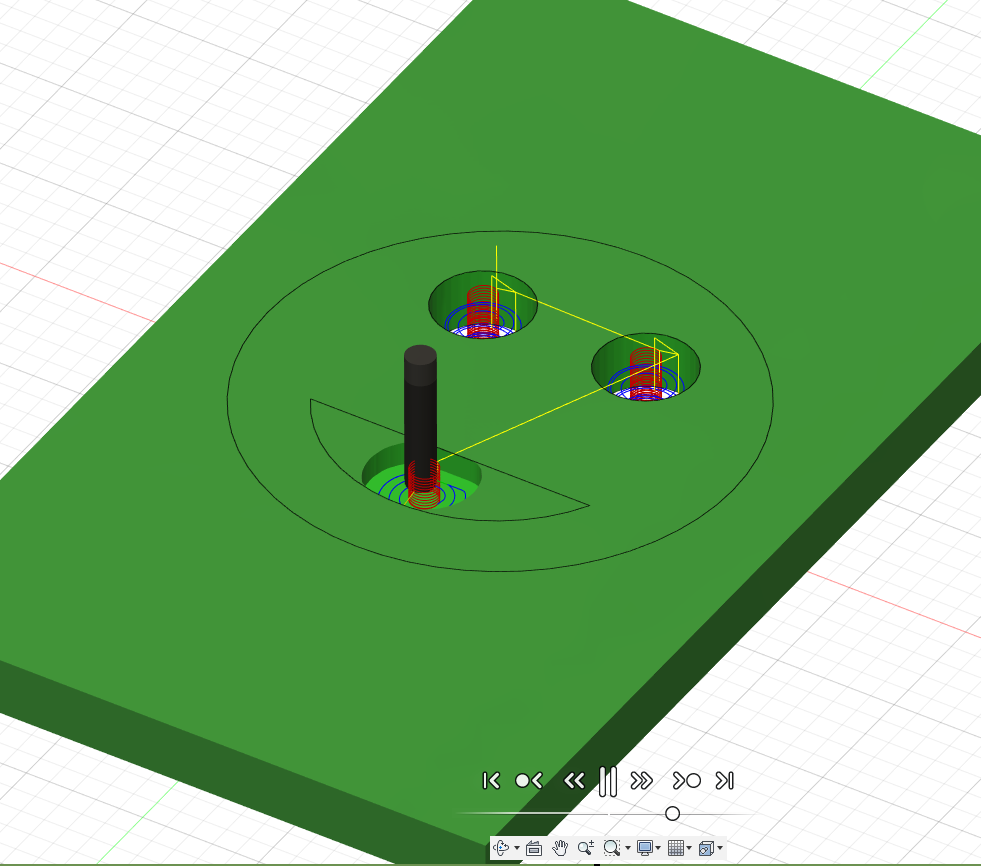
You can now watch how the tool will behave! Press play to watch how the tool will complete the operations you just programed. The yellow line shows how the machine will move in the Z axis, and the green represents the stock that you defined. You should see the material is fully removed from the pockets “through” the stock over multiple passes.
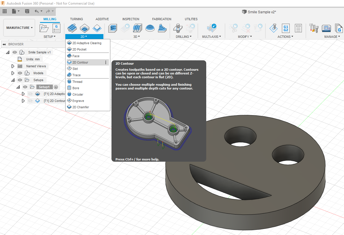
For the 2D contour we’ll follow many of the same steps that we did for the 2D Pocket operations. Follow the same details as shown in Steps 9 through 14 to set up your 2D Contour. Some places to note for different settings are as follows:
Geometry: Under the “Tabs” menu you can specify that tabs will be left on the part ot make it easier to remove from the stock following the cut. This is important because choosing not to leave tabs will result in the part becoming free from the stock at the end of the operation. This can result in the part bouncing and colliding with the bit, ruining the fresh cut part’s edge finish.
Passes: the passes menu looks a little different for a 2D contour. You’ll still want to turn on Feed Optimization and Smoothing. Under “Multiple Depths” you can set the maximum plunge distance like all other parts.
Now your part is ready to go! You can simulate the contour cut just like you did for the pockets. You’ll notice that the tabs we’re left as specified so they can easily be removed after the part has been processed.
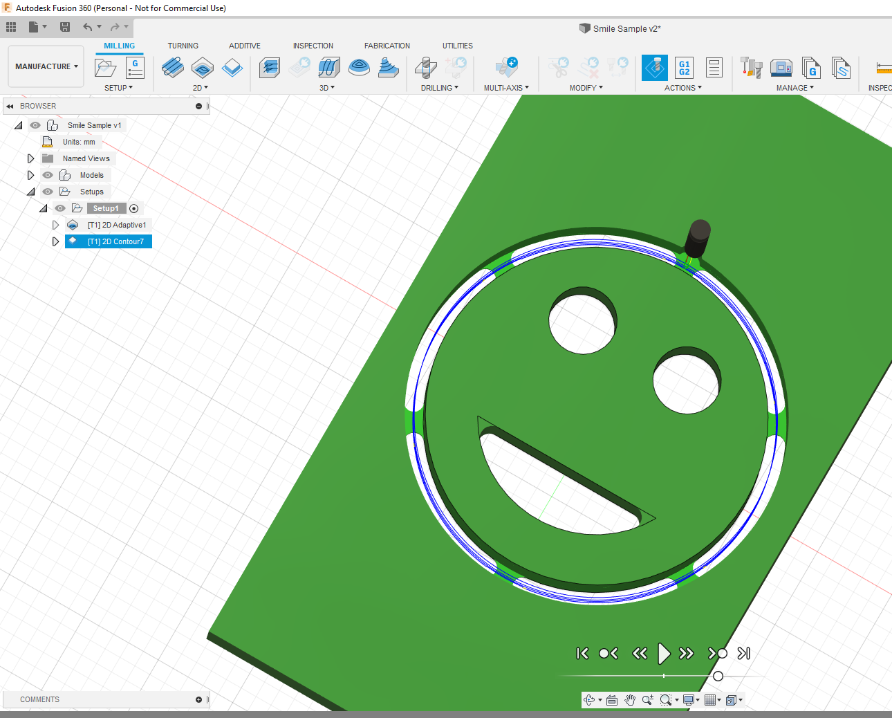
Now that you have completed all the required cuts it’s time to export your machine code. Before you do this it is important to generate your G-Code. This will automatically run through the operations you have specified. If there are any operations that may cause issues the code will throw an error.
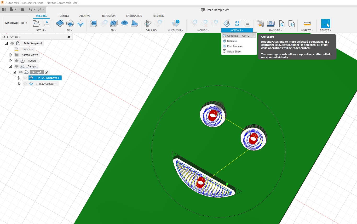
You should generate each step of the machining operation to ensure there are no issues. The code automatically generated after you specify the toolpath, but this is a good sanity check to make sure your part will be cut as intended. Generate each part by highlighting it in the action tree to the left and pressing generate under “actions”.
Now we’ll generate the post process (i.e. the code that the machine will be able to read). Each machine is unique and requires that a specific post processor by used so the code can be interpreted.
If you’re using the X-Carve and haven’t already done so go and add the Easel post process to your fusion 360 library.
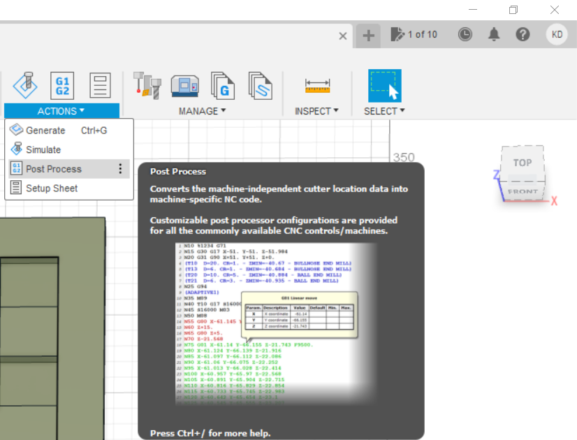
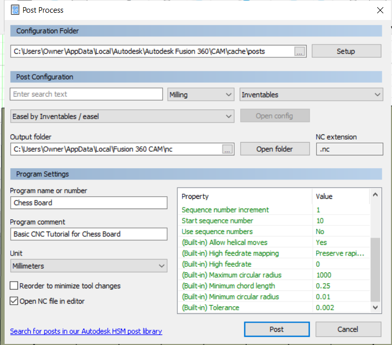
By adding the Easel post processor to the Fusion 360 cloud account you’ll be able to select it form the drop-down menu for post configuration. Here you can also specify the file path where your code will be saved. You cans et up a folder on your desktop and make the default, or navigate to the path that Fusion specifies on your computer
If you’re using the MakerDreams EVO-One. The post processor you use is called: Grbl / Grbl or grbl.cps – Generic Grbl
It’s good process to update the name of the file so it’s easy to find and change your default path to a place where you’ll be able to navigate to it. After adjusting the settings press “post”. This will generate the NC code for you to view if you’ve selected it as an option to open. Each line corresponds to an operation completed by the machine.
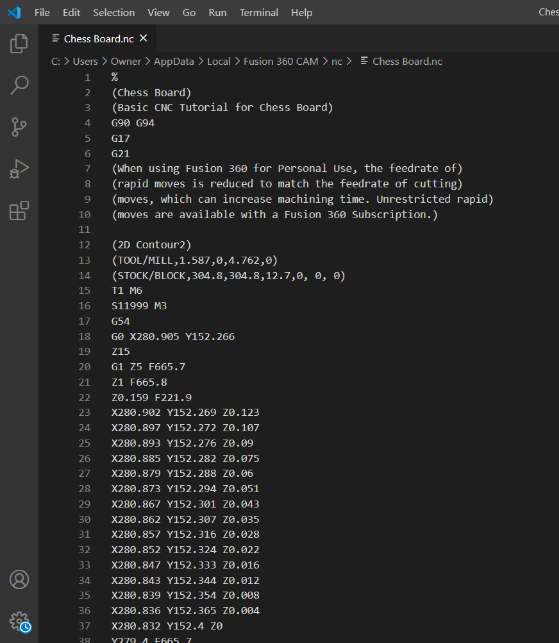
That’s it! Proceed to the next tutorial to learn how to set up the CNC and launch the GCode on either the X-Carve or Evo-One!