Setting up the EVO-ONE
Read Before Operating - Evo-One Mill Quick Start Guide
Safety & Operations Notes:
DO NOT handle any bits for this machine without GLOVES. The BITS are extremely SHARP.
To change a BIT, follow the tutorial linked below.
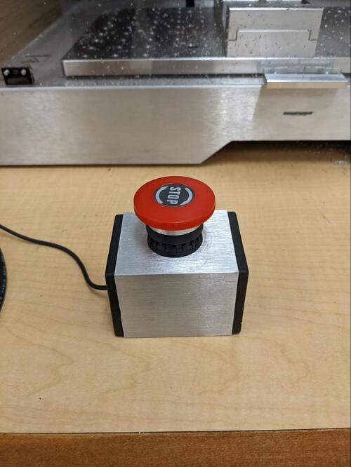
There is an e-stop connected to the rear of the machine, this will cut power to the operations if there is an issue.
DO NOT leave this machine unattended while running.
A computer with Cre-Mov must be connected to the mill to operate it. If the computer enters standby so will the Mill.
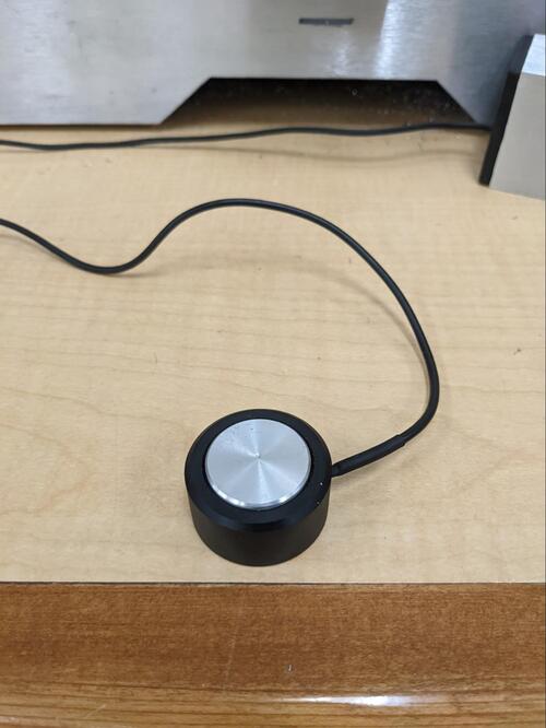
There is a z-probe connected to the rear of the mill that can be used to zero the z-axis of the system before starting any operations.
Make multiple shallow cuts instead of large cuts. This will be easier for the machine to handle and have less of a chance of damaging the machine or the stock.
The E-stop must be disengaged before operating. If you are getting no response from the machine, the button is likely pressed.
Mill Tutorial: https://munsdh.readthedocs.io/en/latest/CNC%20Mill.html
Overview:
A mill is a computer numerically controlled machine that uses a rotating spindle to remove material. To make use of this mill one must download the Cre-Mov software from the makerdreams website.
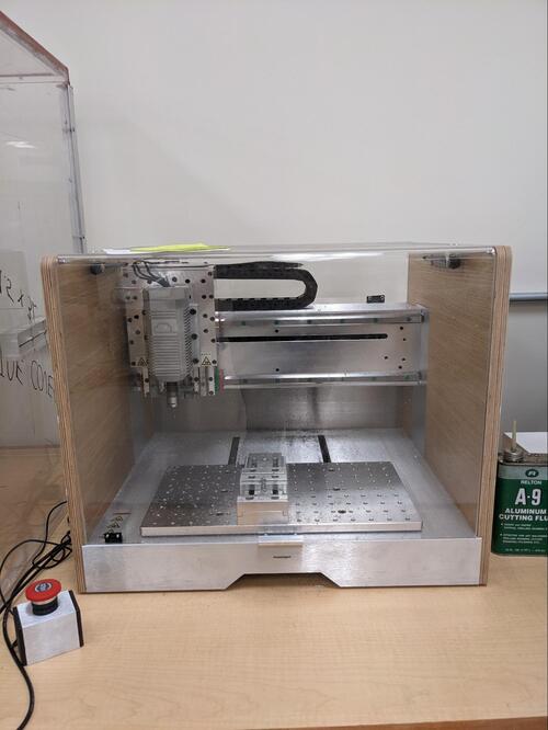
Make sure the lid is properly closed before operating. There is a safety built into the cover that wills top the mill mid operation of the lid is lifted. Do not try to open the lid and touch the mill during operation.
The Z-offset must be set before cutting. Use the Z-probe attached to the machine to set the Z-offset. Here is a guide with a video on using the z-probe: https://docs.sainsmart.com/article/yhgowhcb8x-what-is-a-z-probe-how-do-i-use-it
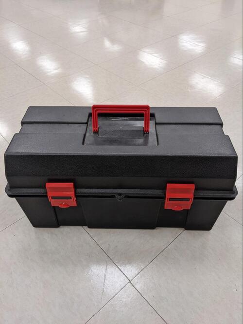
Secure your stock. There are clamp supports and screws located in the black box below the table the mill is sitting on. These screws/clamps can fit into the aluminum bed and keep the stock secure.
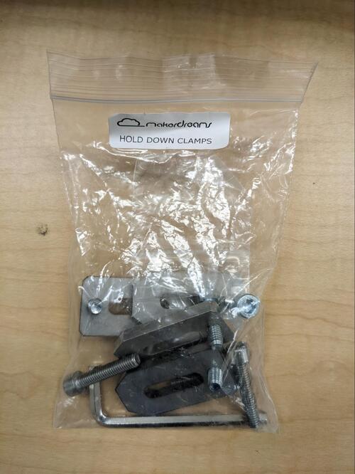
There is also a vice and a frame that can be screwed into the bed to hold the stock. Make sure to account for the thickness of the spoilboard and the vice / clamps in your toolpaths. This may limit some vertical operations and the maximum travel in the z-direction. .
Feeds and speeds can be determined using the spindle RPM and the tool diameter. A handy calculator can be found here Free CNC Speeds and Feeds Calculator.
When processing aluminum you may need to use a cutting fluid. Use shallow cuts and cutting fluid on the bit periodically to ensure the best possible surface finish.
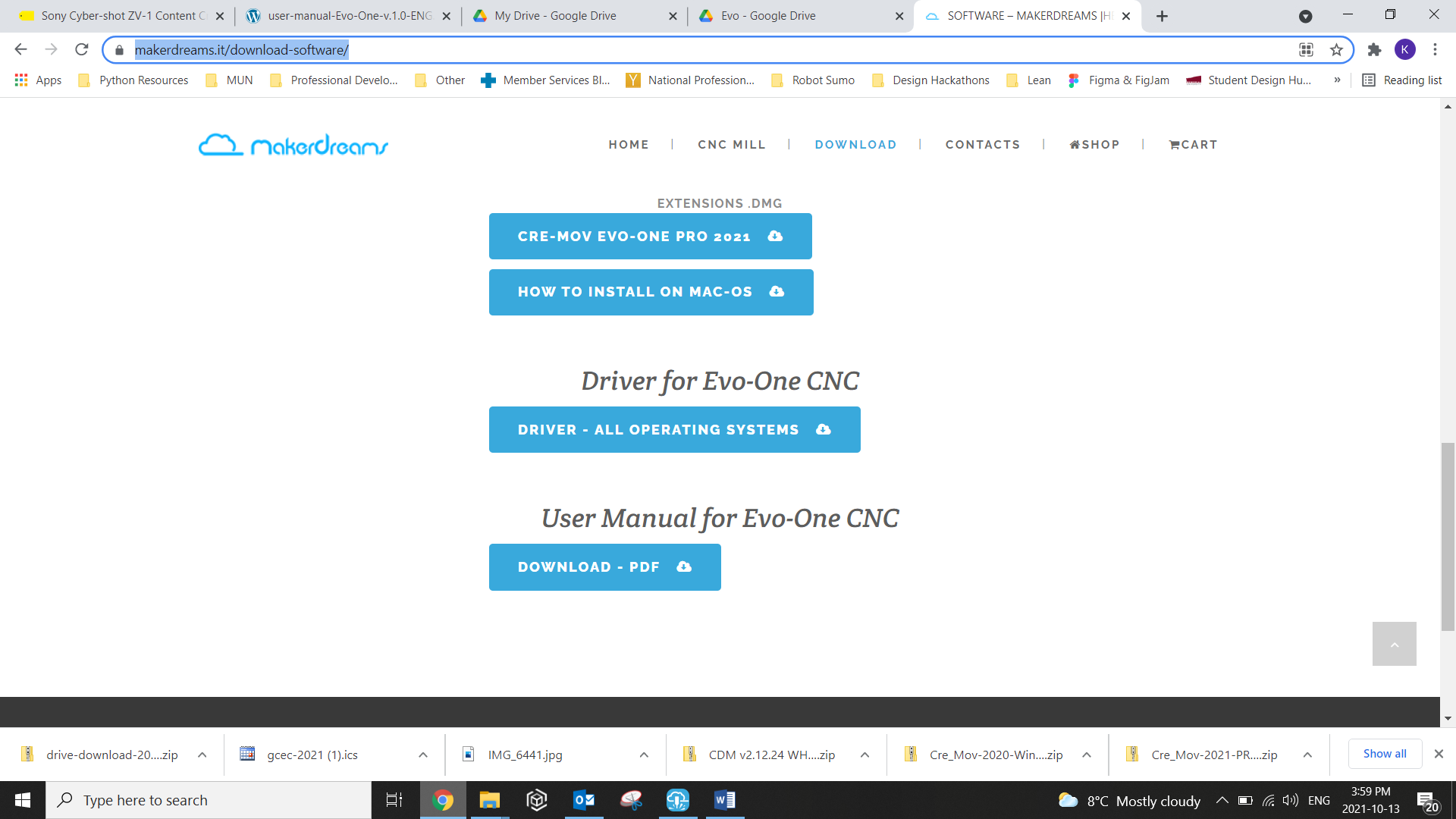
The fist step to using the Evo-One will be installing the Driver on your computer. The machine will automatically install the driver when you connect to it by USB. However, it can also be installed on the MakerDreams webpage: https://makerdreams.it/download-software/
Measuring Your Stock
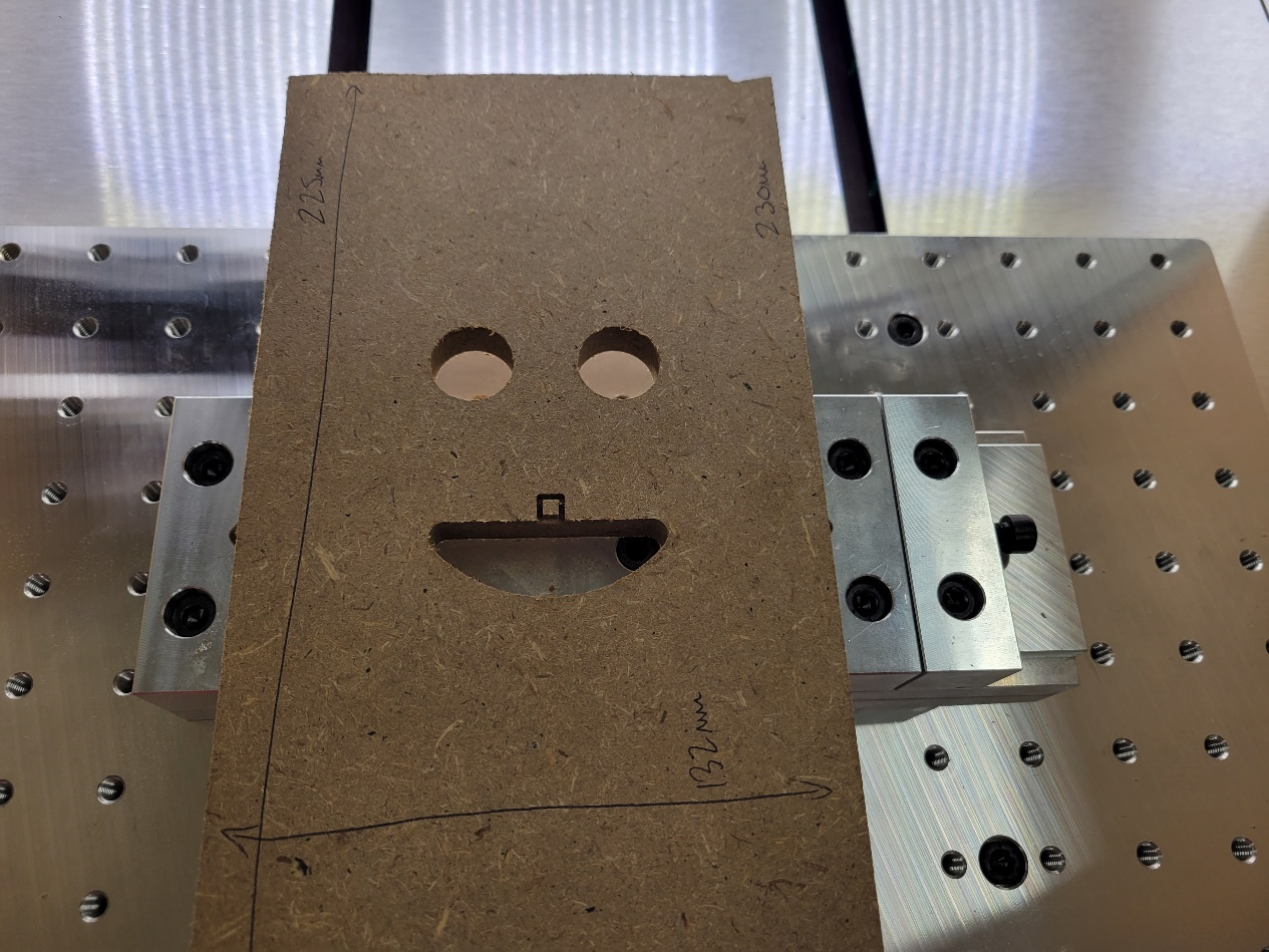
Before you do anything you need to ensure that you’ve set up your stock correctly. Grab the measuring tape (or a set of calipers) from the toolbox and do a check of your material size: The effective stock size we have for this cut is 225mm x 132mm (at 12mm thick)
Secure your stock
You can secure the stock to the bed in two different ways. The first is by using the machine clamps. To secure the part using the machine clamp. Use the fllowing steps:
Secure the clamp to the bed using the three mounting screws along the clamp base. It is best practice to mount the clamp in the center of the bed.
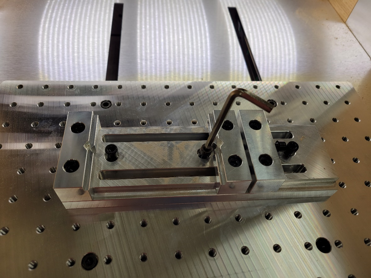
Open clamp all the way to allow stock to be secured. The maximum width of the clamp is 13.3cm.
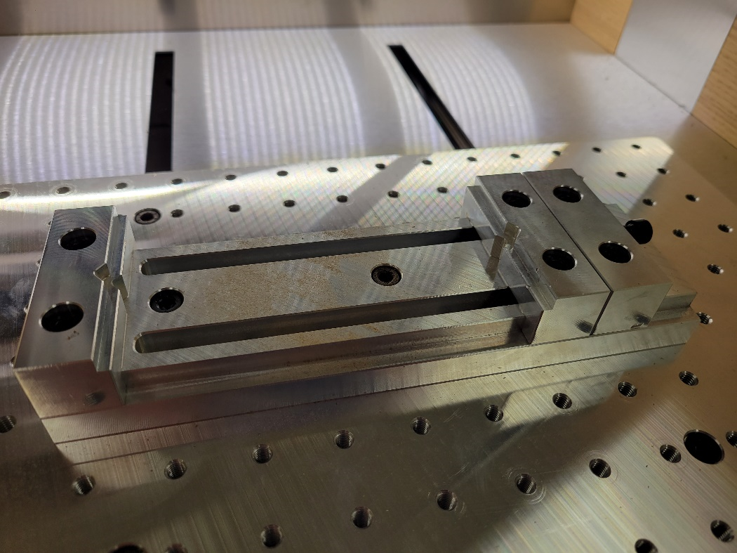
Set the stock in the clamp. There are two ways to set the stock. On the raised edge, or on the base. In this case we’ll set it on the raised edge.
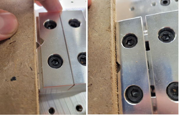
Move the inside clamp jaw in and tighten it in place. The stock will sit on the clamp but can be easily removed. Ensure the stock does not exceed the length of the bed.
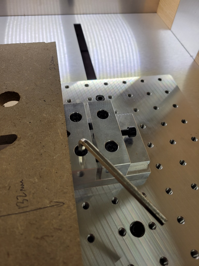
Move the outside clamp in against the inside clamp. Tighten it in place.
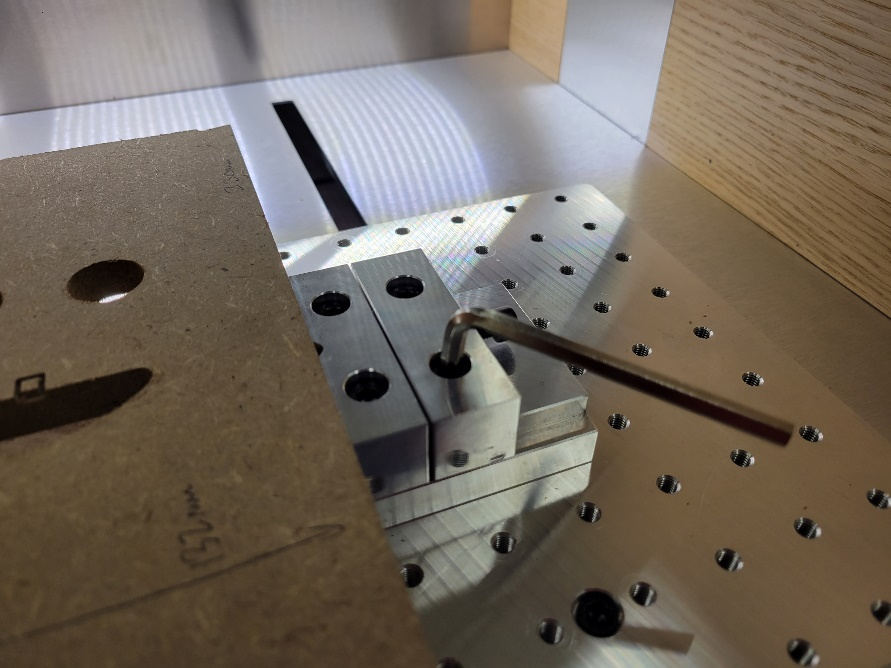
Tighten the outside set screw. This forces the inside clamp against the stock. The stock should now be secure.
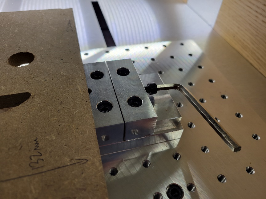
The second way to secure your stock is by mounting it directly to the bed oft he machine. To secure the part directly to the bed. Use the following steps:
Its best practice to use a spoil board when doing any operations on the CNC Mill. The purpose of the spoil board is to ensure that the bed is not damaged in the event a bit travels through your part. Spoil boards are easy and inexpensive to replace!
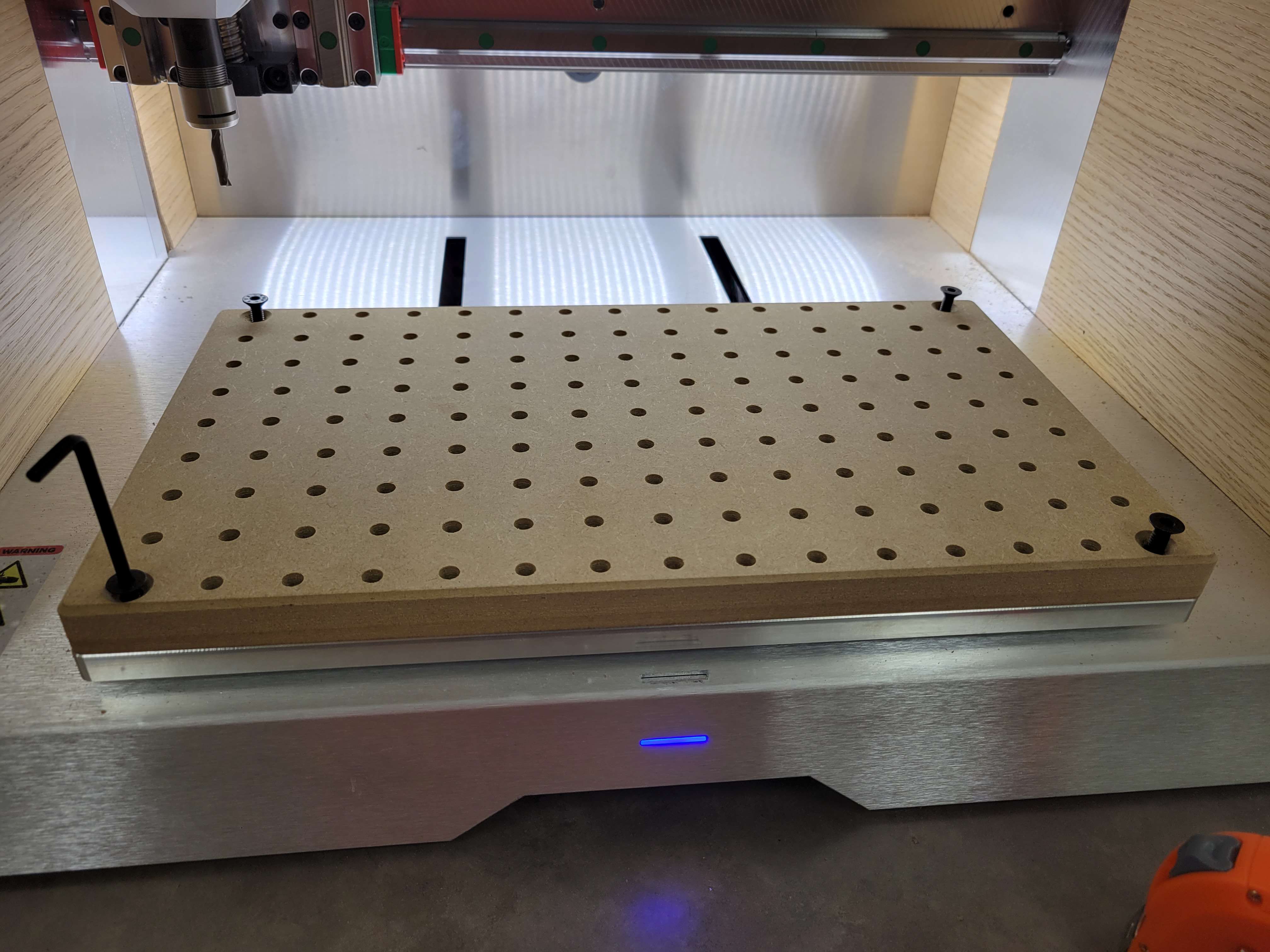
Ensure the spoil board is secured to the bed using the four mounting screws (one on each corner). For the remainder of this tutorial the part will be shown as clamped without a spoil board. The SDH needs to order longer mounted screws to accommodate for the thickness of the board.
Materials are secured to the bed using machining clamps. A machining clamp has a slot and a threaded hole.
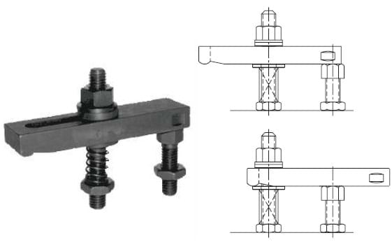
The purpose of the threaded hole is to create an adjustable stand off from the bed. Thread the shorter bolt through the threaded end of the clamp until the side with the socket is the same length as the part thickness you are planning to machine.
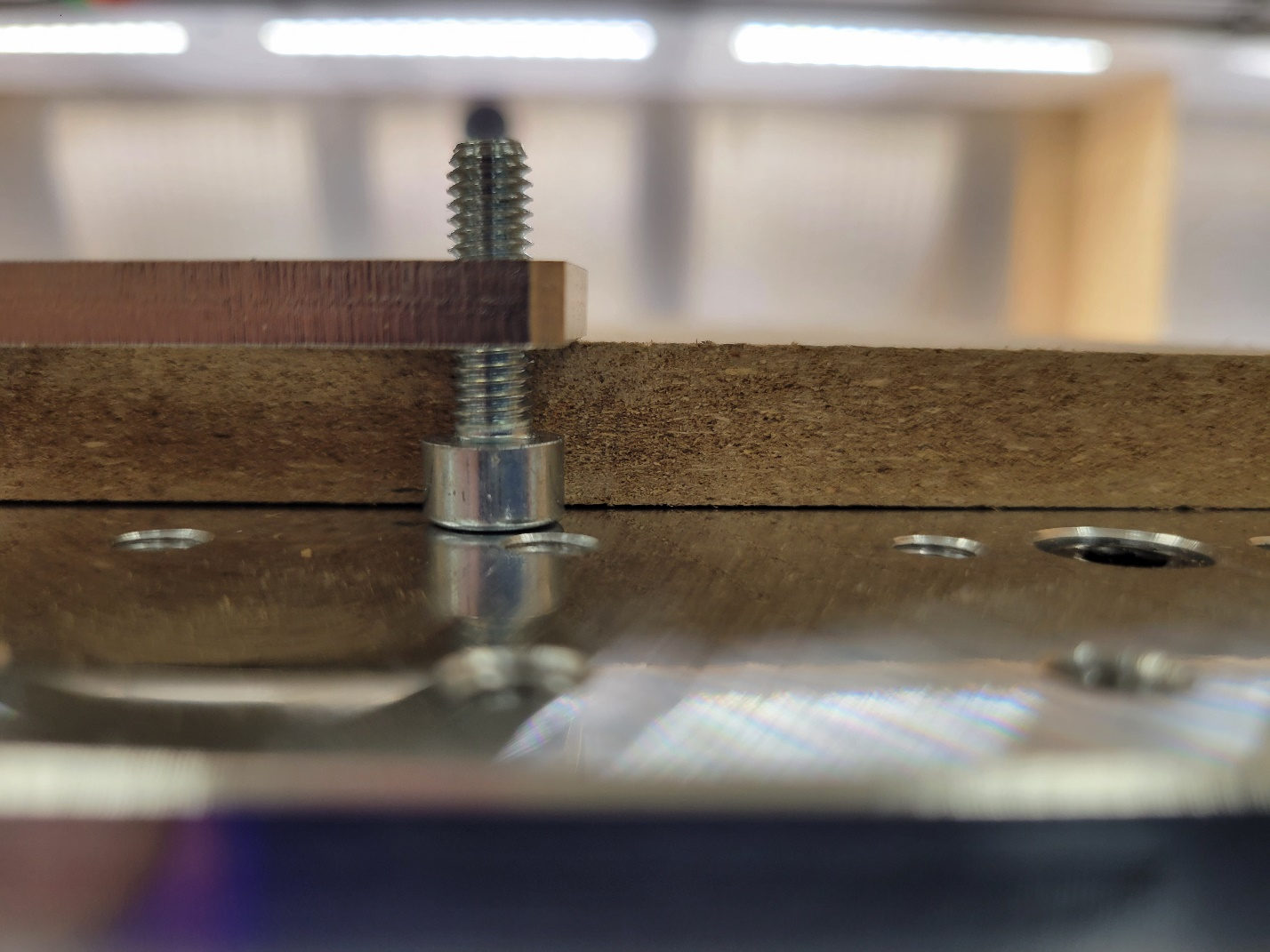
The next step is to secure the clamp to the bed. You do this by using the longer bolt and the slot on the top of the clamp. Run the bolt through the slot and thread it into one of the threaded mounting hols on the bed. Leave some slack in the bolt so the clamp can be moved along the slot.
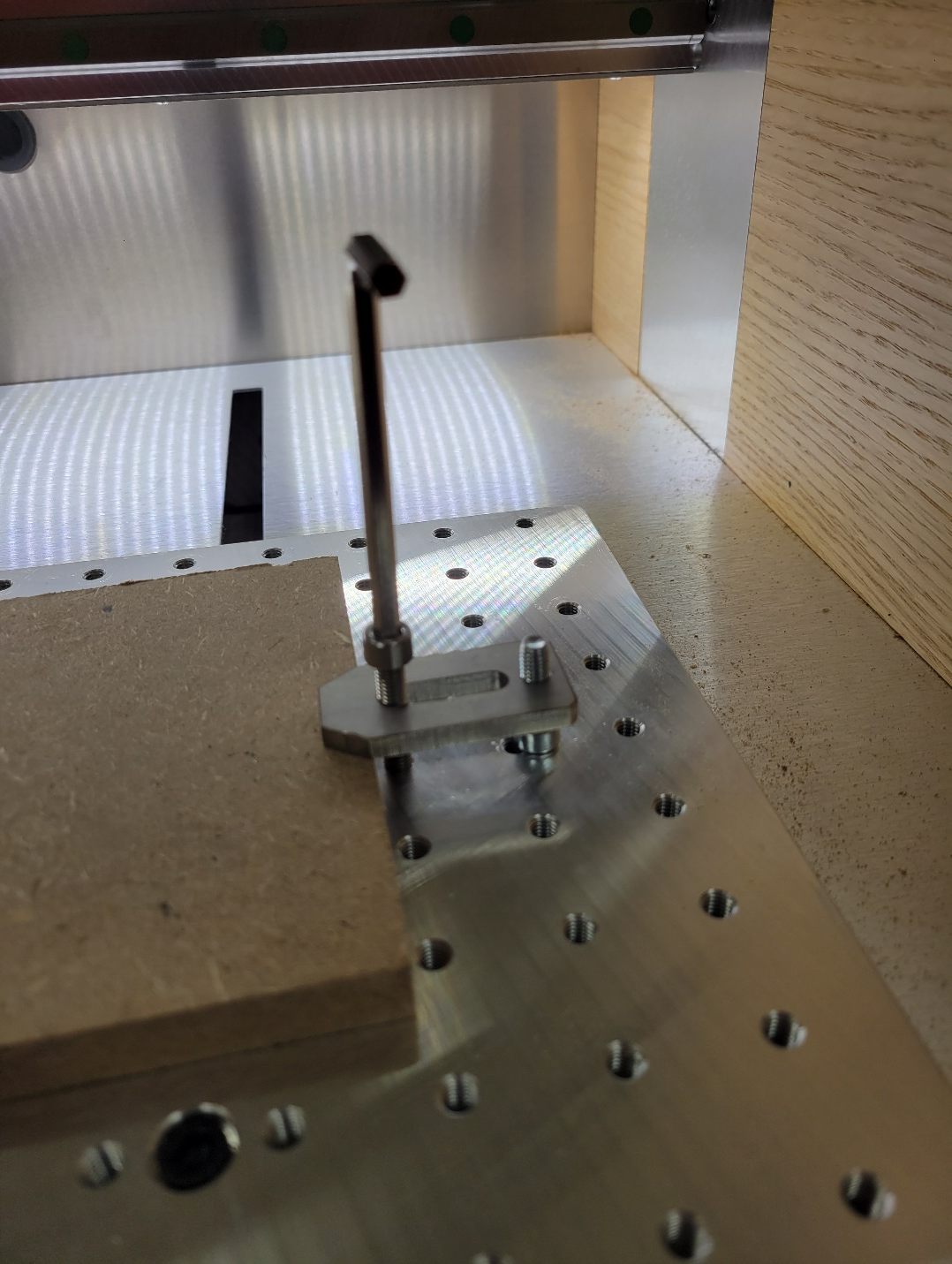
Next repeat this process for the remaining clamps you plan to use. Its best practice to use at least four. This will stop your stock from shifting in the X or Y directions when being milled.
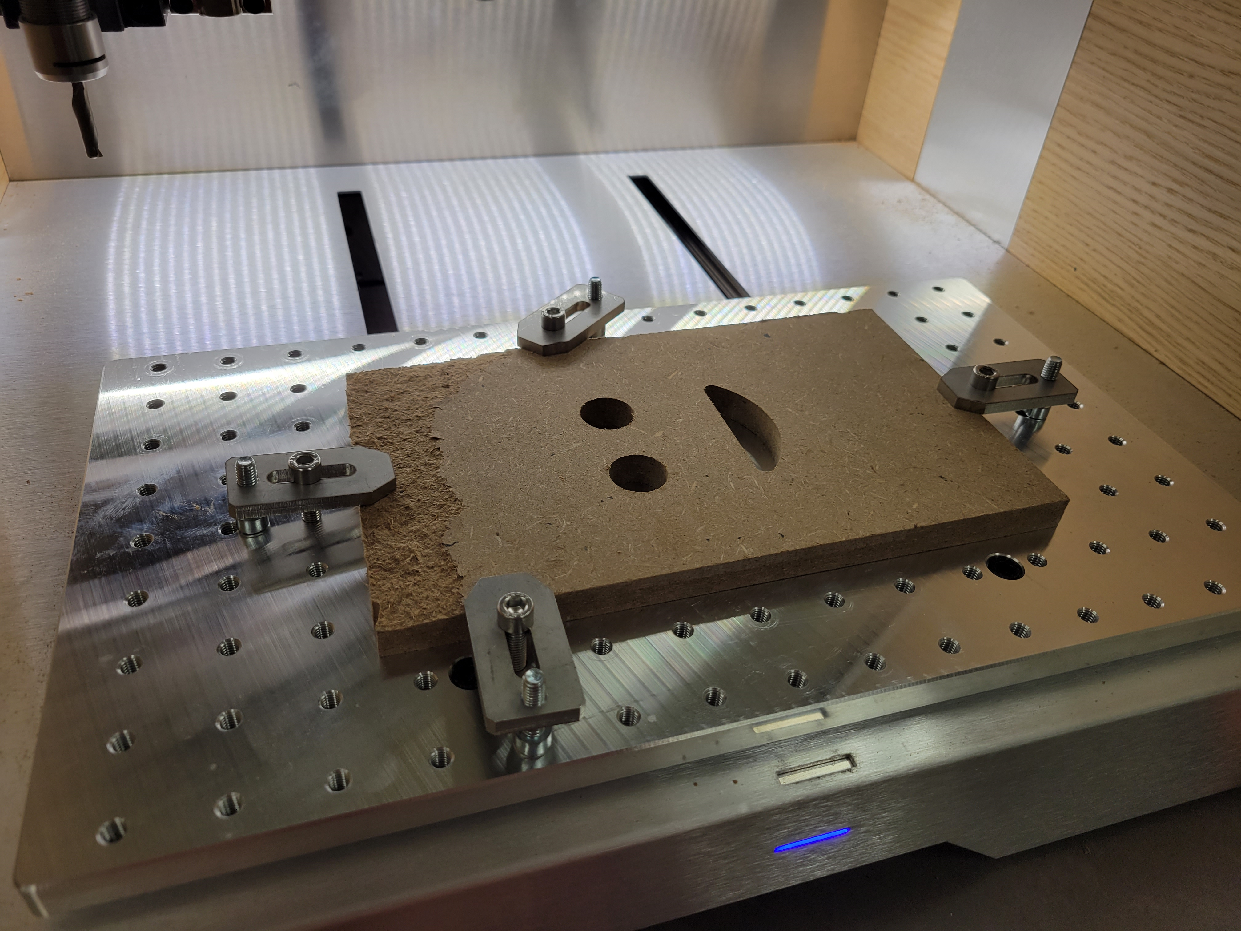
Tighten the four clamps such that the stock is secured! Ensure that you keep an even boundary around the material so that your bit does not drag through the clamps during operation. A good practice is to measure how far each clamp protrudes across the surface of the stock and then set that as a boundary in your toolpath.
REMEMBER! Although not shown, a spoil board is REQUIRED. Photos will be updated when longer mounting hardware is available.
Changing the Bit
CRITICAL! Turn off the machine!
Safety Reminder: Mill bits are very sharp, only handle the bits with cut proof gloves.
The EVO-ONE is a great machine because it offers a variety of collets to suite most appropriate bit sizes. This means that multiple diameters can be used for cutting with minimal effort. There are a variety of bits and collets available in the lab, if the bit you need is not available, check to see if the collet is available or the machine. If it is, the bit you required can be purchased for the lab at no cost to you.
Remove the Collet Holder. To remove the collet holder you will need a wrench and a spanner. The wrench is placed on the upper part of the assembly (on the spindle), and the spanner on the lower part (collet holder). You’ll know where to place each one based on the shapes of the tools. To loosen the collet holder, twist the wrench CCW, and the spanner CW. The handles should push towards each other.
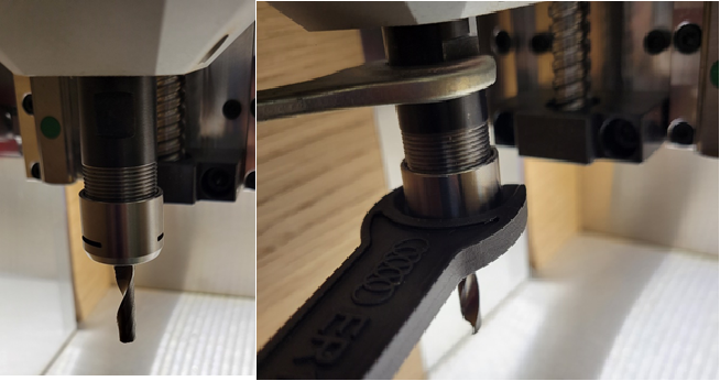
The collet holder should now be able to move freely on the threads of the spindle head. Carefully unthread the collet holder from the spindle. Do not old the assembly by the bit! The whole assembly should then come free from the spindle.
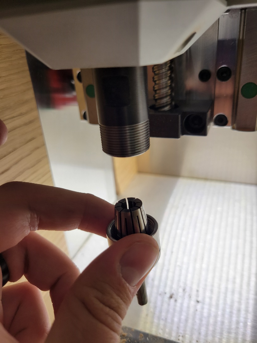
Now that you have the collet holder in your hand you’ll notice that the collet itself floats in the holder. Remove the collet and bit from the holder and place the collet holder to the side.
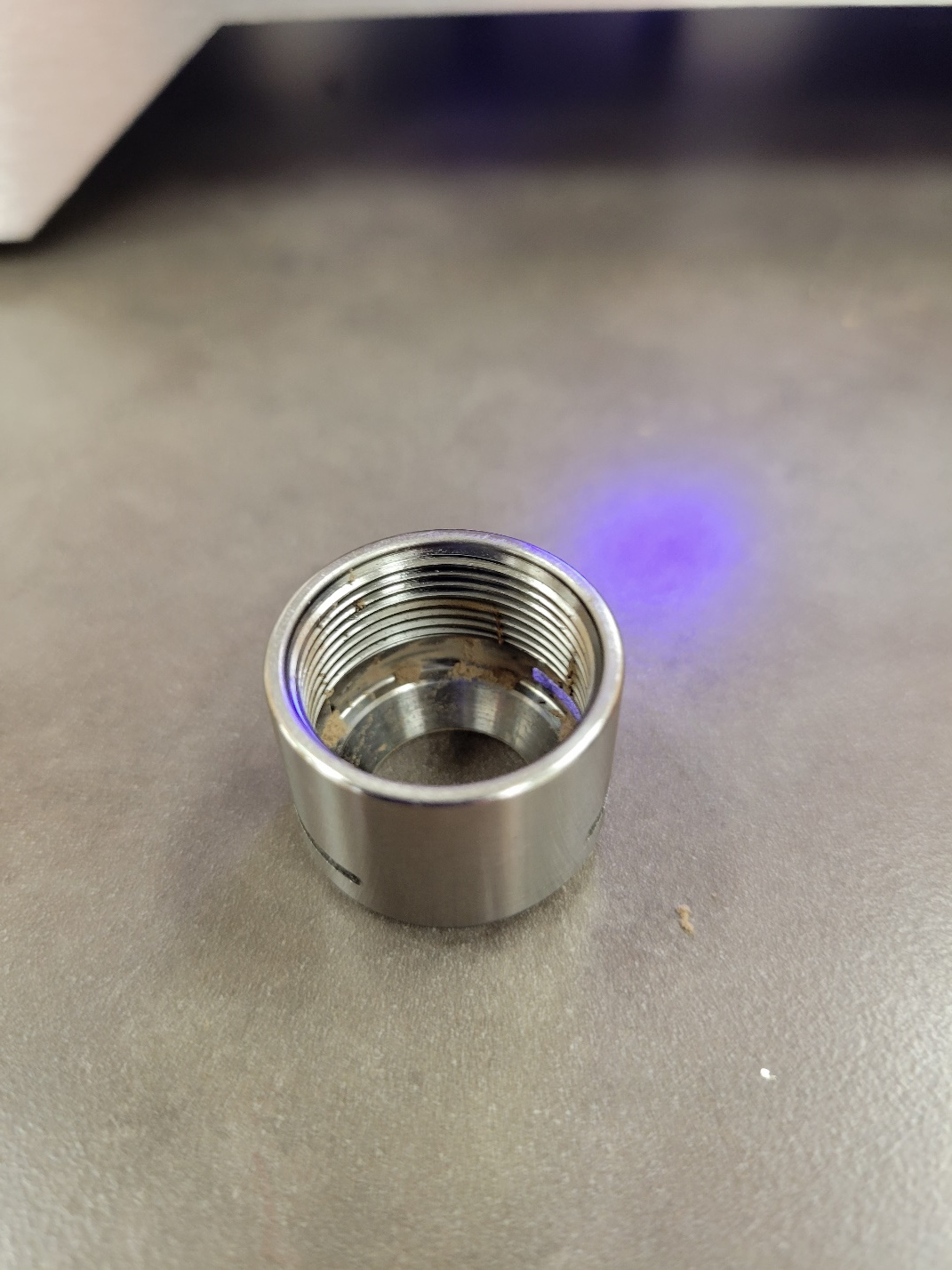
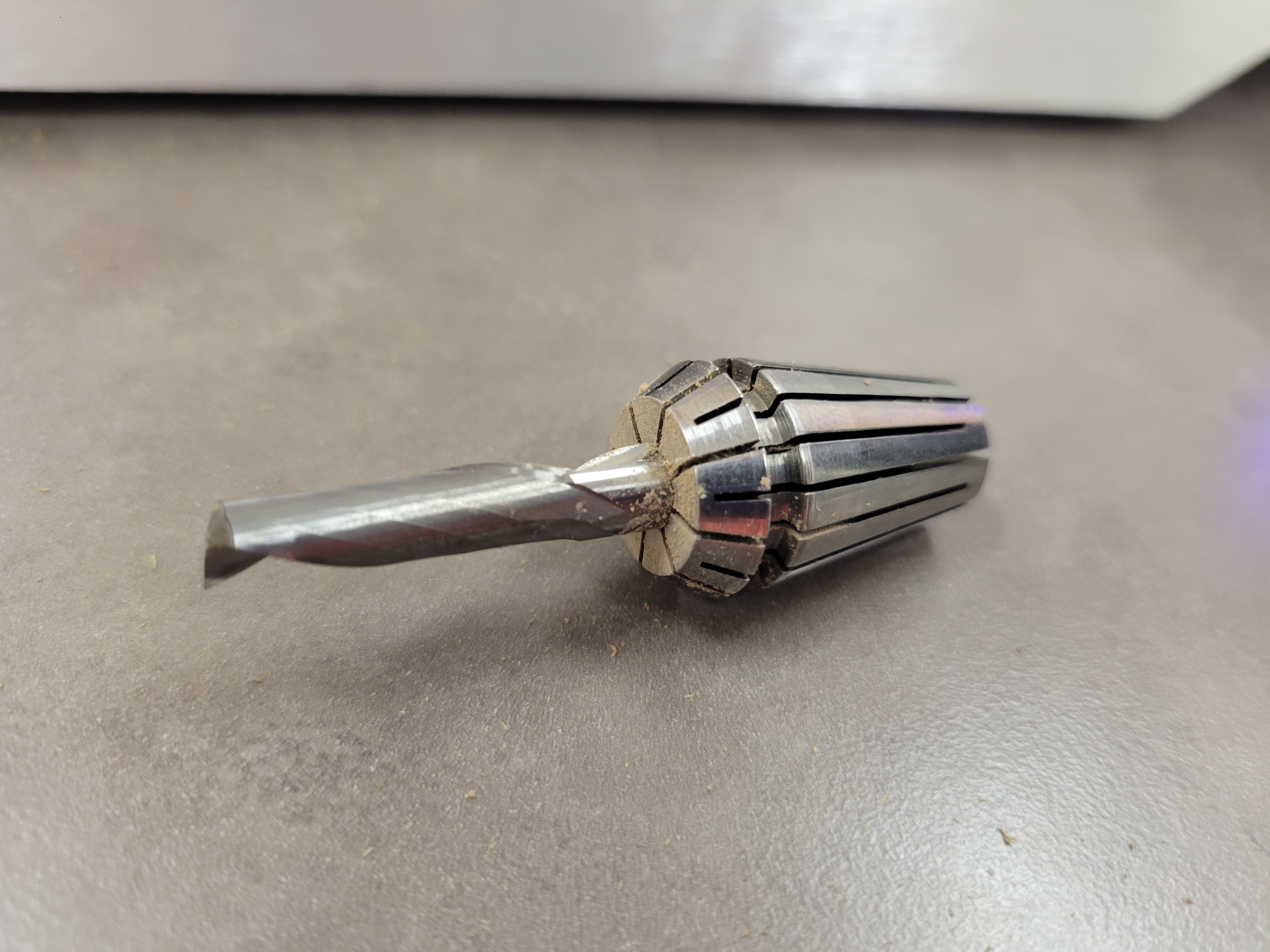
Now you’ll have the collet and a bit. The bit is very sharp so only handle it when using cut proof gloves (in the toolbox with the x-carve). The bot sits in the collet by friction, put on the gloves and remove the bit. You can also push the bit through the collet by using a narrow cylindrical object (like the insert from a pen).
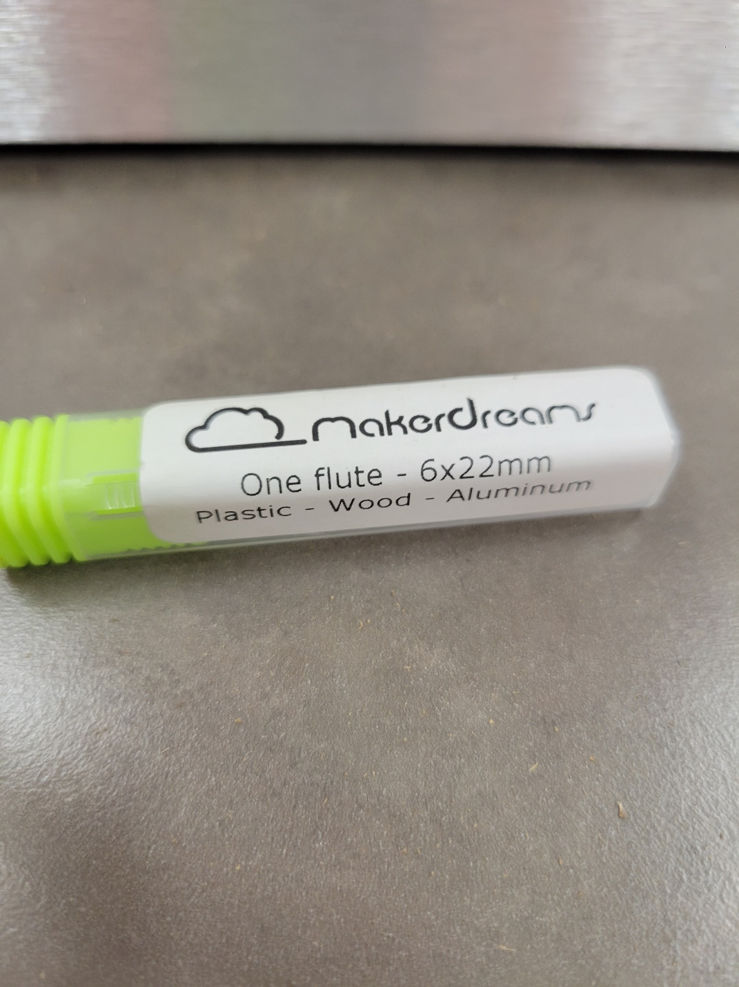
In the Evo-One toolbox there are all sorts of bits and collets available for use. Since the bit sits in the collet by friction, you need to make sure the bit you select matches the collet. On each bit container there is a description of the bit. The image below shows a 6mm bit that’s 22mm long. To use that bit, you would need the 6mm collet.
Carefully install the bit in the collet. The b it can sit anywhere in the collet. Ensure that the cutting surfaces do not extend into the collet body. The part of the bit inside the collet should be the solid shaft. This is an appropriate time to enter the bit details in your Fusion 360 tool library! Measure per the instructions on the library to ensure your toolpath is mirroring the bit exactly.
Now that the bit is in the collet, place the collet back in the collet holder.
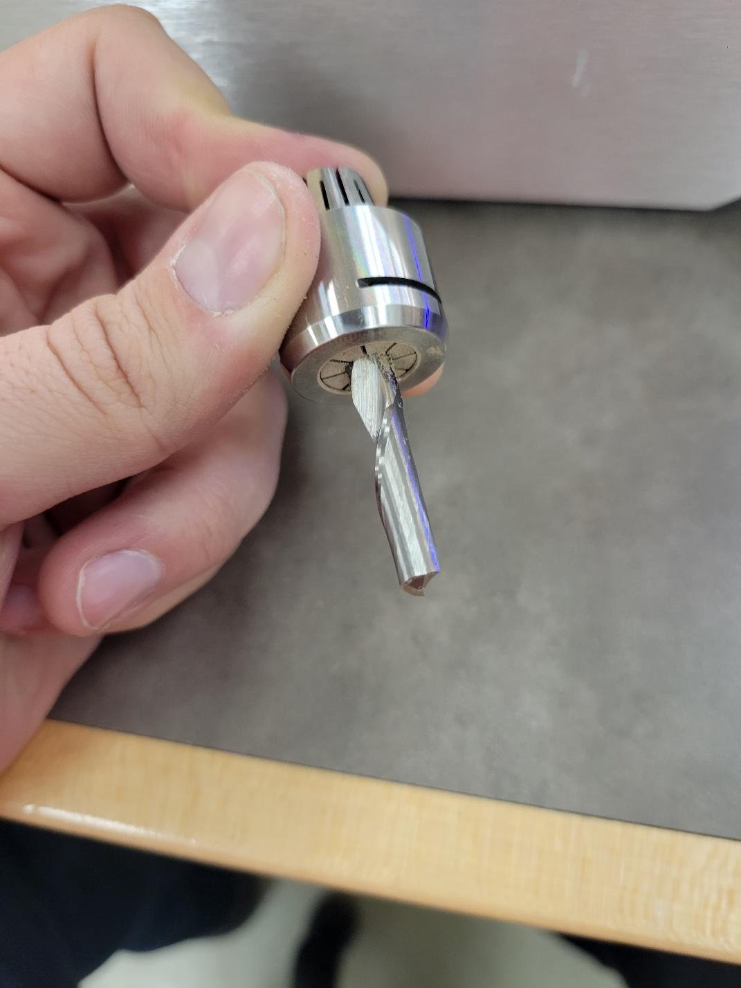
Thread the collet holder back onto the spindle head. Thread the holder up until you start to feel resistance. The collet holder threads CCW.
Similar to how you removed the collet holder, install the spanner on the holder and the wrench on the spindle. To tighten the collet holder, twist the wrench CW, and the spanner CCW. The handles should push away from each other. Tighten the spindle until it provides a decent amount of resistance (don’t overtighten too much as it could deform the threads, it should feel firm).
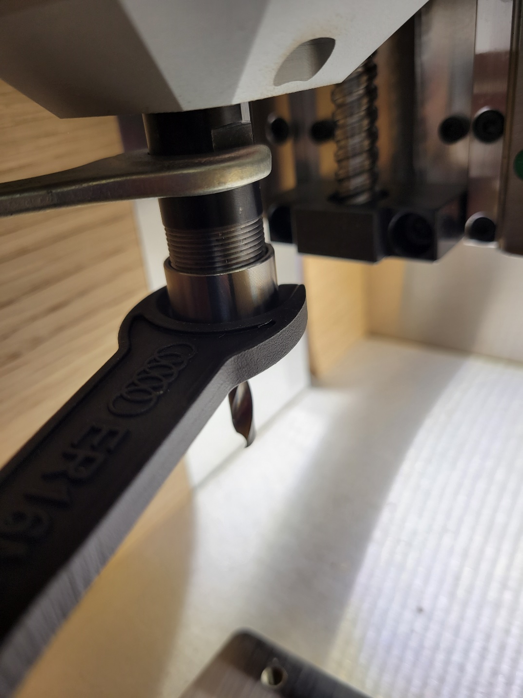
Now you’re ready to start cutting!
Evo-One Importing G-Code to Cre-Move & Making a Cut
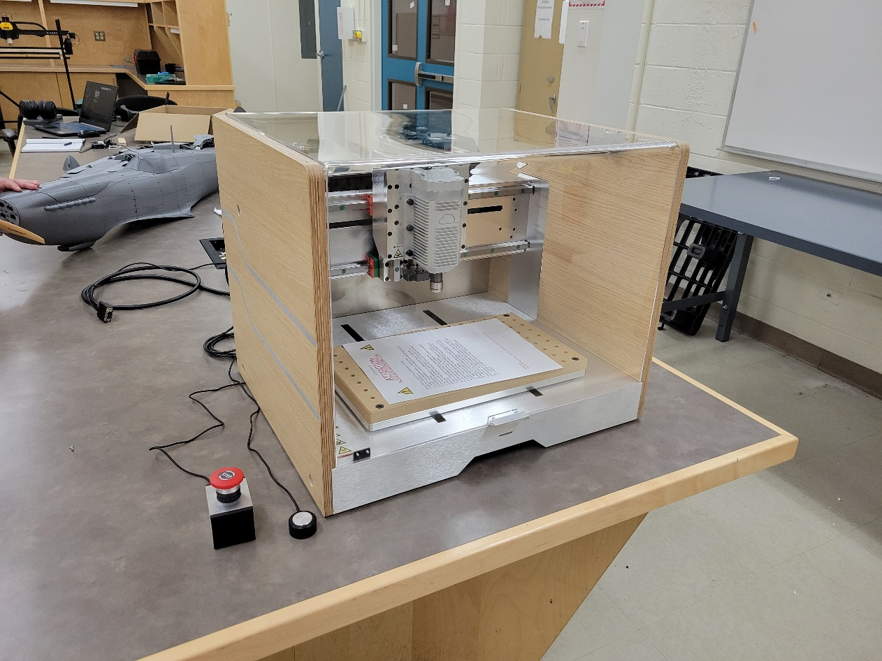
Turn on the Computer
Plug in the E-Stop and Z-Probe
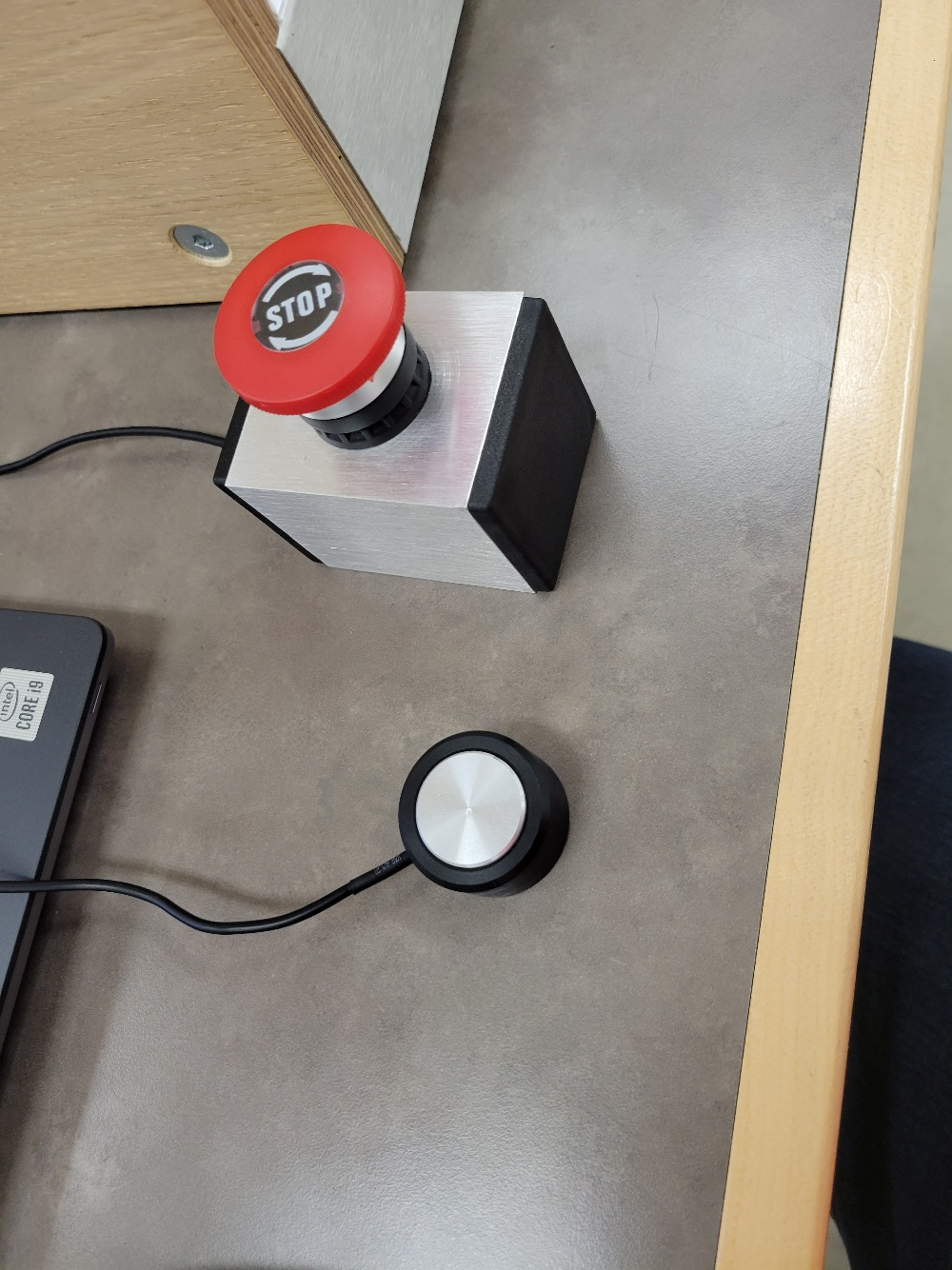
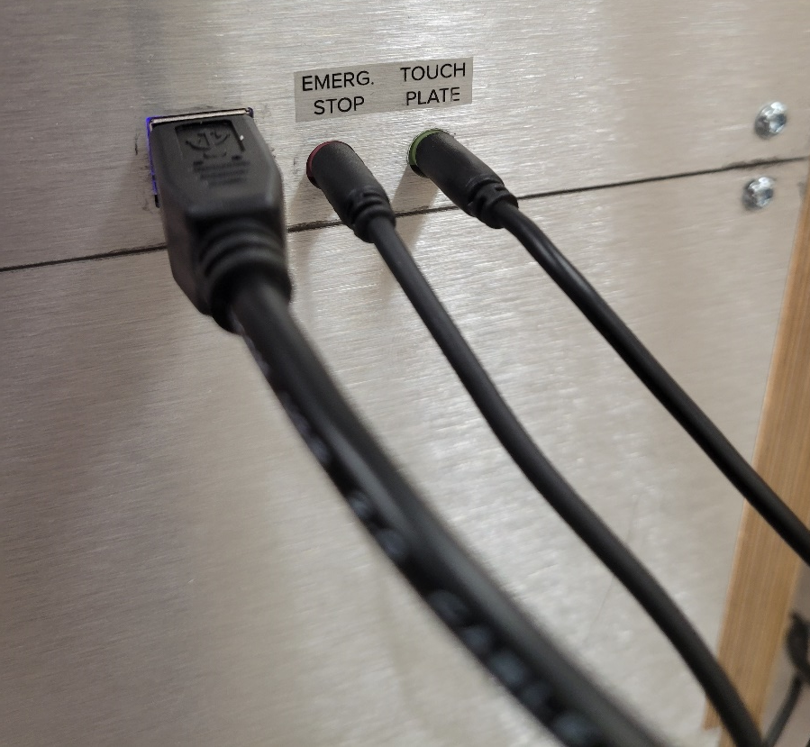
- Connect the PC by USB, wait for Drivers to Install
If drivers do not install automatically visit: https://makerdreams.it/download-software/
Power on the machine by pressing the power switch
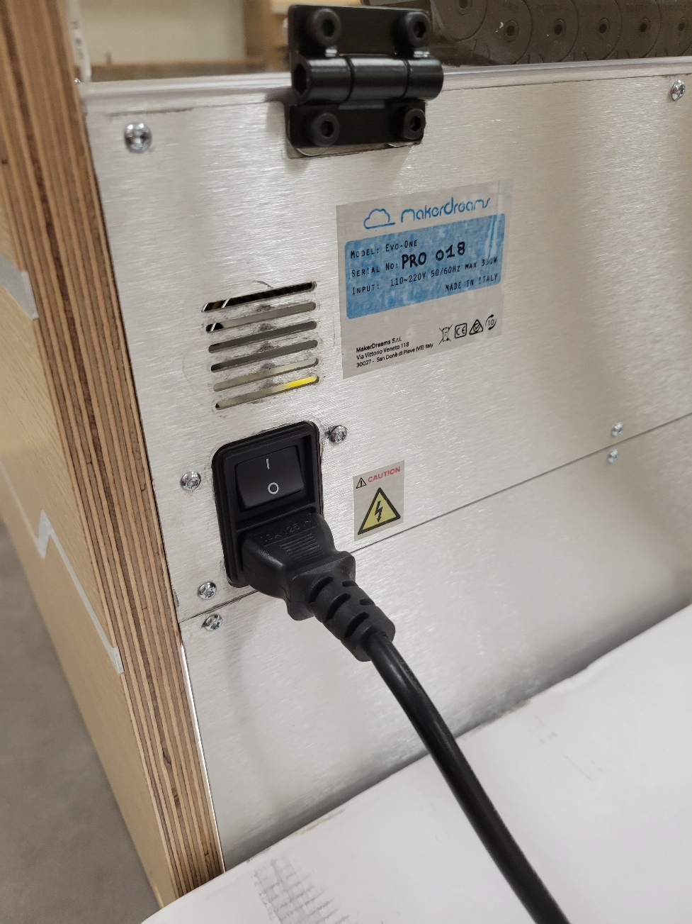
- Launch Cre-Move
You can download Cre-Move from the Makerdreams site: https://makerdreams.it/download-software/
NOTE: unzip the folder and save it somewhere on your computer. The EXE file must be run from the folder with the reference files or it will not move
NOTE: Download CRE-MOVE PRO 2021
NOTE: Cre-Move’s UI doesn’t stretch with resolution. It works best on a 1080p screen (for laptops) or on a computer monitor.
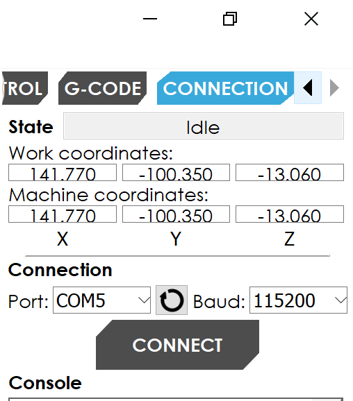
In Cre-Move under “Connection” connect to the machine
Navigate to the Control menu, the machine will show an Alarm. Press Reset. Then unlock the machine.
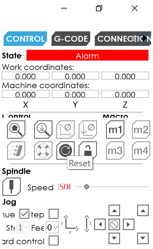
Next hit the home button to teach the machine where the machine zero is. This will teach the machine where X:0, Y:0, Z:0 from a machine reference should be
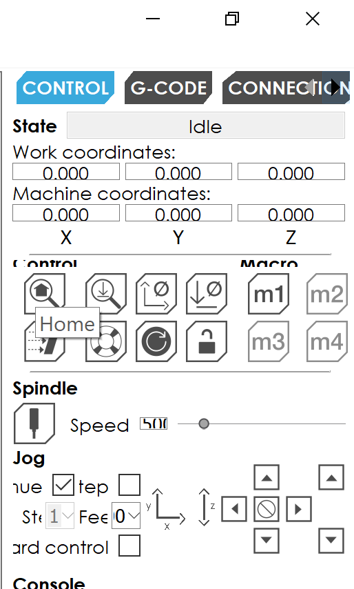
- Next jog the machine so the spindle is directly over the stock. You can jog the spindle by using the directional buttons on screen. There are two movement options:
Continuous: The spindle will move while the button is pressed
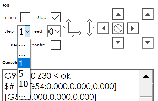
Step: The spindle will move by the specified step number
Continuous is great for getting the machine in the general position quickly. Then you can use step to precisely move the spindle. Move the machine at 1 step for higher accuracy, and 10 steps for quicker repositioning.
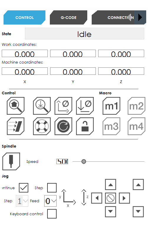
Zero the machine in the z-direction by placing the probe directly under the bit. Then press Z-Probe. The machine will touch the probe and then move back to the top of its reference geometry. Now the machine knows the z-position of the stocks surface.
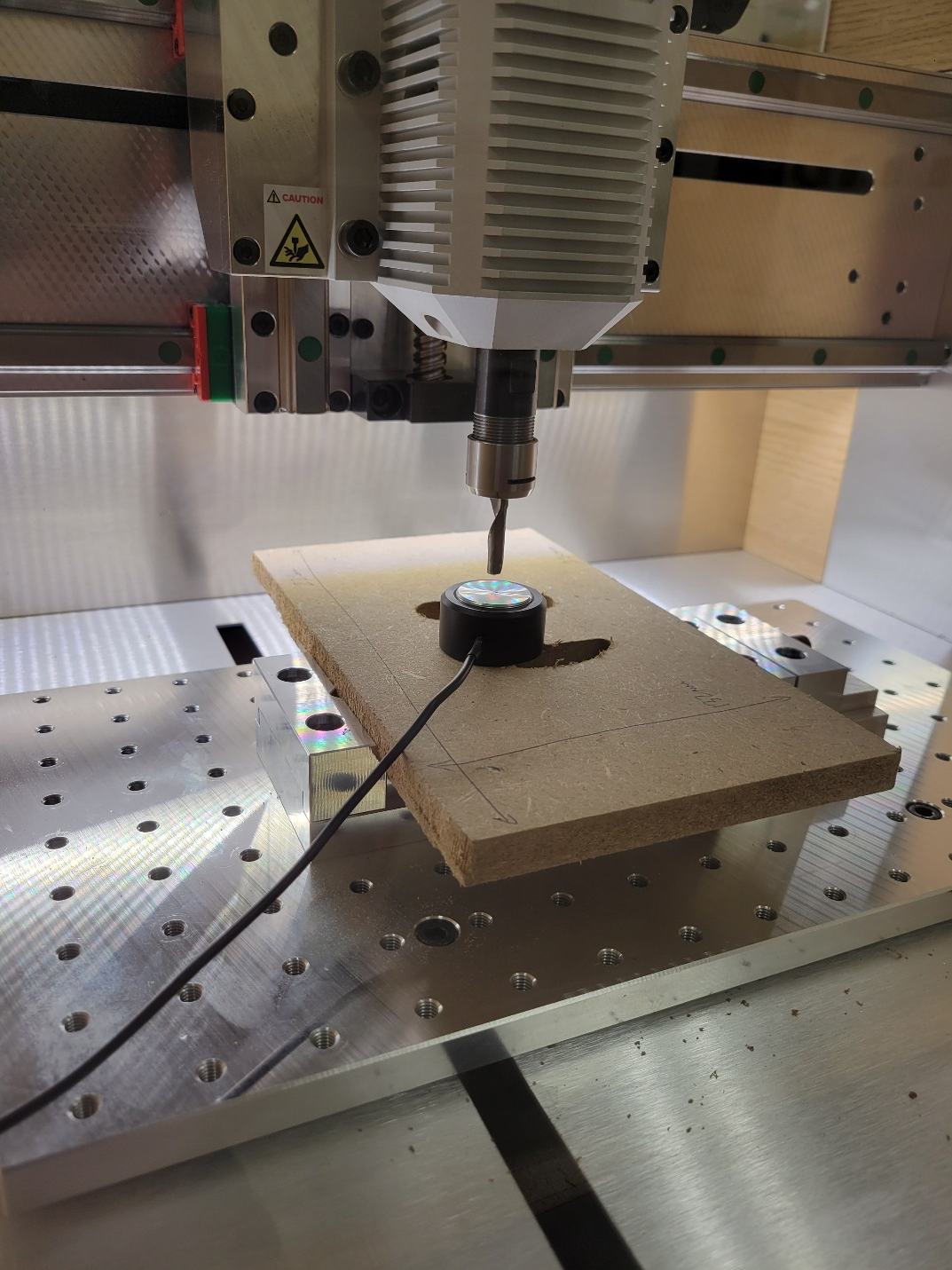
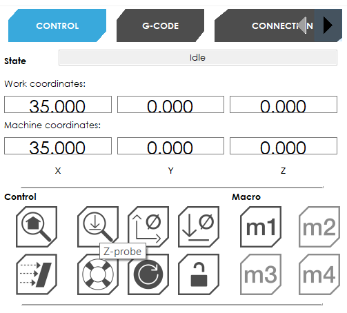
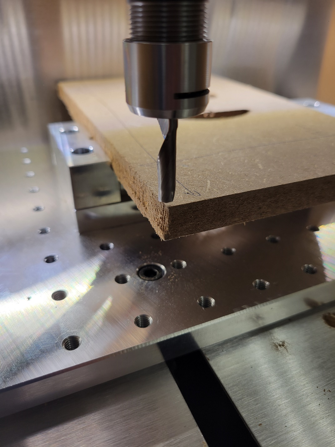
Next zero the x-y axis by moving the machine to the bottom left corner of the stock. This should be the x-y position of the origin in your gcode. Look back at your toolpaths to determine where you set the stocks origin to be. In this case it’s the bottom left corner of the stocks top surface. Try to align the center of the bit with the corner of the stock.
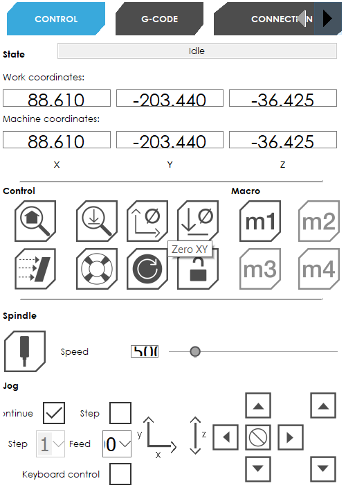
Now you can import your GCode. Go to the G-Code tab and press Open. Navigate to your G-Code exported from fusion 360 and select it. The g-code will preview in the screen to the left.
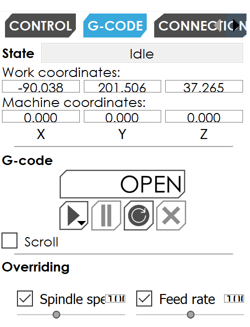
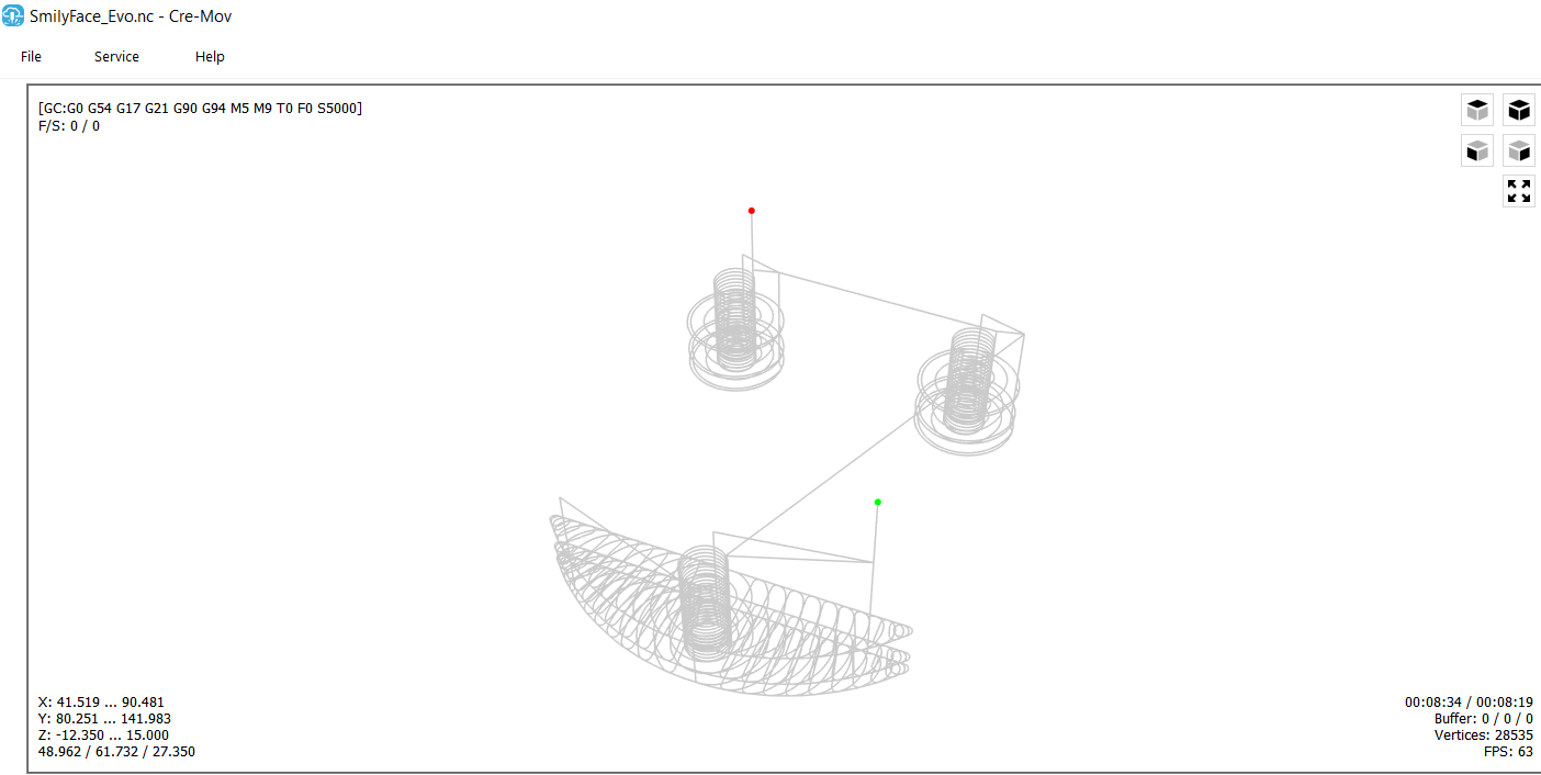
If the preview looks correct, press Play and watch the machine do the rest!
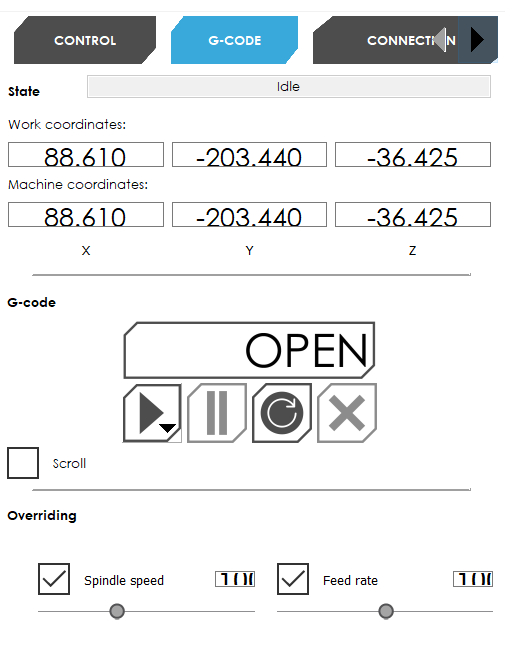
NOTE: if the machine is behaving in a way that doesn’t look correct, or it is going to damage something press the E-STOP!
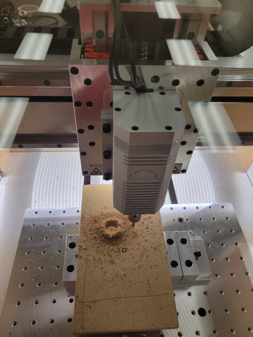
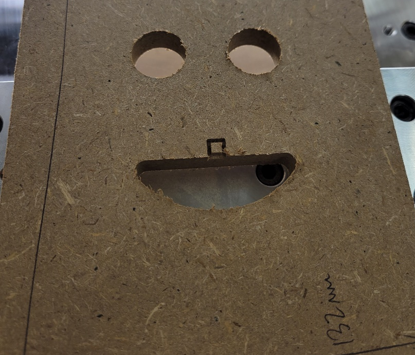
Smile! You made your first cut on the MakerDreams Evo-One!
