Test Apparatus
A DAQ is a highly praised measuring device mainly due to its versatility, a DAQ is operated using a wall power source and can come with a handful of chassis controller types for different kinds of connectivity such as wifi, ethernet or USB. The chassis is also easily transportable for mobile use due to its compact frame and is designed to withstand harsh environmental climates in temperatures as low as -40०C and as high as 70०C, making it easily usable even in restricted or remote work conditions. Finally, the greatest upside to using a DAQ is the broad range of sensors that are available to use with the device. The DAQ uses modules that plug directly into the device to connect whatever sensor that is being used to analyze data. With a wide range of modules with different outputs, the DAQ can handle a large variety of sensors for measurements for (but not limited to) voltage, current, acoustics, temperature, pressure & load.
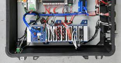
DAQ Chassis
The DAQ chassis being used in the experiment is NI’s DAQ model number 9174. This particular model belongs to NI’s family of compact chassis DAQ’s or cDAQ’s which are a smaller, more portable line of NI’s DAQ system options. The 9174 in particular has 4 module slots and uses USB 2.0 to communicate with a PC as seen in the cDAQ diagram below (for access to the datasheets, click here).
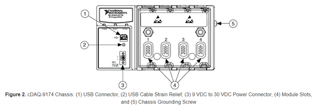
As seen in the diagram, there are 5 important components to the DAQ:
USB connector: Used to connect the provided USB type-B cable to collect & deliver data to a computer.
USB Cable Strain Relief: Threaded hole to screw in proprietary USB cable to relieve tension in the cable & protect the internal conductor or the plug/connector & cable connection.
Power Connector: Power insert for power delivery to the cDAQ.
Module Slots: Inserts for C Series I/O modules.
Chassis Grounding Screw: Threaded hole to allow for a wire to be attached to the chassis to ground the device and provide added protection from current caused by electrical shorting when in contact with the device.
Load Cell
For our apparatus we are using a force transducer (also known as a Load Cell), a sensor device that takes any force or load value placed on it and delivers the measurements as a voltage output. These voltage outputs will be received by the DAQ as an analog input and converted back to a force value as a digital output into LabVIEW for data analysis.
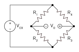
The circuit configuration being used in the Load Cell is known as a “Full Bridge”, a type of wheatstone bridge configuration. Wheatstone bridges are a fundamental type of electrical circuit and are used to measure electrical resistance. In the case of the load cell, these bridges are used to accurately measure the voltage fluctuation caused by the load cell when it experiences deformation. This voltage value, which is an electrical analog signal, is then transferred to the DAQ where the module then converts it to a digital output signal that is then transferred to DAQExpress to be measured & analyzed.
For the experiment, we will be using a Durham Instrument’s SSB-AJ-100 load cell capable of measuring up to a 100 lb load. The data sheet for this sensor can be seen below and will be referred to throughout the tutorial when needed to verify some of the sensor’s parameters during the experiment and can be accessed at the link here. Manufacturers will provide data sheets such as the one shown for the load cell below for their products which can be accessed by contacting the manufacturer or sourcing the sheet from online resources. Equipment data sheets are essential for equipment configuration in DAQExpress and are essential when attempting to record measurements.
Data Acquisition Modules
While DAQ chassis is highly important it is only responsible for housing the devices, the job of actually converting sensor measurements into readable data belongs to DAQ modules. These modules are hot-swappable devices that are the component of the CDAQ responsible for measuring different signals & mediums and converting them to voltage & current inputs. Modules are used in tandem with the chassis and act as a sort of “all-in-one” system for converting analog-to-digital or digital-to-analog data before it reaches the chassis, since all of the necessary circuitry is included inside the module. Modules are also capable of communicating with other devices through digital input/output modules and can be used for signal conditioning.
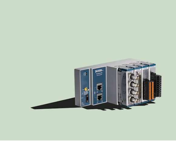
As previously mentioned DAQ systems are very versatile mainly due to the wide array of available modules that can be used to communicate with a wide array of industrial devices, with modules models differing depending on the type of connector that it uses to communicate with. For this experiment we will be sticking to NI’s universal analog input module the NI-9219.
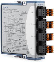
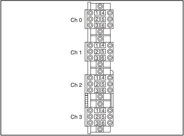
The module shown below specifically has 4 spring-terminal connectors, with each connector having 6 number pinout terminals from 1-6. Each one of these terminals is also given a distinguishing number from 0 to 3 known as a “Channel”, as seen in the module diagram below.
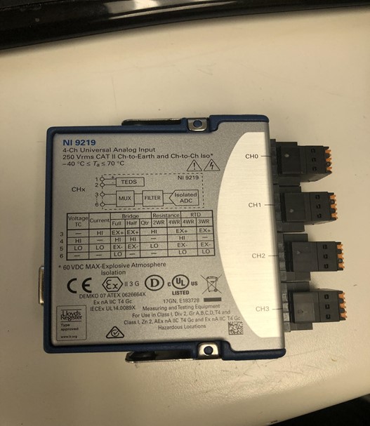
The reason that the NI-9219 is a “Universal” input module is because of its ability to accommodate multiple circuit & wiring configurations. As mentioned previously in the Load Cell section, the sensor incorporates a “full bridge” circuit configuration to provide the voltage measurements needed to measure the load on it, however the module is capable of handling multiple circuit configurations such as half or quarter bridges (commonly used in strain gauges), 2-wire, 3-wire & 4-wire resistance circuits, thermocouple sensors, and many others. For a list of all circuit configurations along with the wire terminal placements for compatible sensors, click here.
Software
For the sake of this tutorial, the goal is to get a general understanding of how to set up the DAQ and utilise NI’s application software called DAQExpress. DAQExpress is NI’s proprietary software and will allow us to analyze and interpret our measured data sent from the DAQ. DAQExpress is not only able to measure & record data, but can also be used to create control systems & feedback loops that can be iterated and analyzed using both simulated data and recorded data.