Oscilloscope Probe

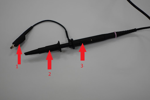
Ground clip of probe. The ground clip must be attached to the ground in the circuit to receive accurate results.
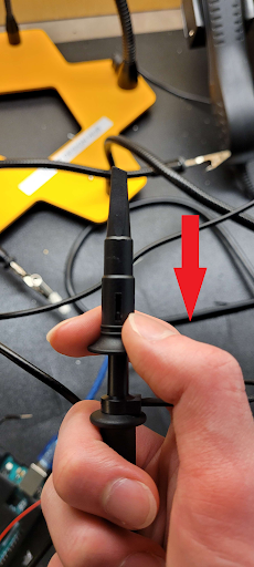
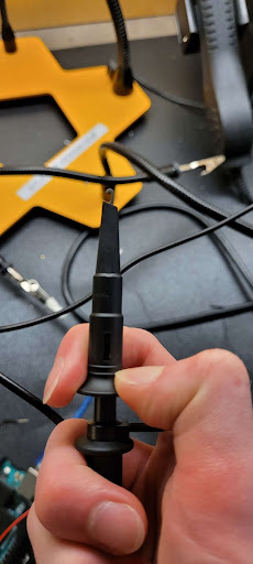
Oscilloscope probe. Pull down on the sheath to reveal the probe underneath.


Switch to choose between a 1x or 10x multiplier. This switch control is a scale factor that the probe will use to measure the waveform on the screen. By default, it is 1x. It is important to note that the 10x setting should be used for frequencies over ~1MHz, as the electronics inside the probe will skew the results at frequencies this high.
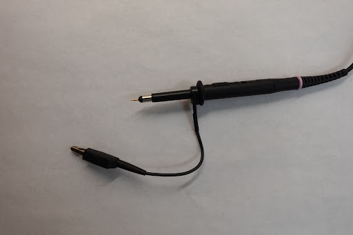
The tip comes off the probe, and you can use the contact inside instead of the clip.
