RIGOL DS1102Z-E
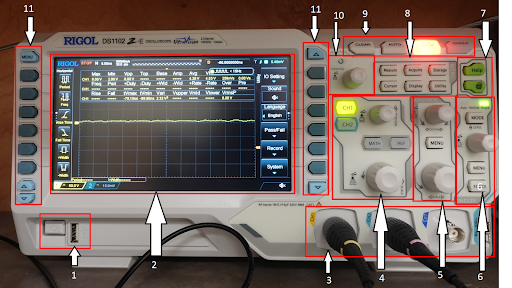
The POWER button will turn the oscilloscope on or off. Next to the power button is a USB(Universal Serial Bus) port used for saving screenshots of waveforms.

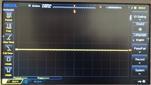
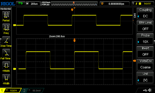
Screen showing UI display.
The two analog inputs on the left are for measuring analog signals, and the third is an input for an external trigger.

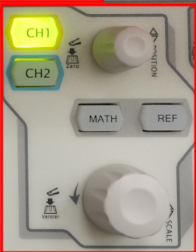
When pressed, the two buttons on the left, CH1(Channel 1) and CH2(Channel 2), will enable or disable the channels on the oscilloscope. If either of these buttons is green, then the corresponding probe is on, and it will show up on the screen as a flat line by default. If the channel is off, the button will have no colour and will not show anything.
The POSITION knob will translate the wave vertically without changing its scale. Clockwise for up and counter-clockwise for down. The position of the waveform will briefly appear at the bottom of the screen when using the knob. Pressing down on the POSITION knob will reset the waves back to the middle of the screen. This is useful if the wave gets too far off the screen or to measure the position of the wave from the origin.
When pressing the MATH button, the right side of the screen will have MATH functions appear. Using these functions, the user can calculate the current or power in a circuit. To calculate the current, measure the voltage drop across a shunt resistor and use ohms law I = V/R.
The REF button will generate a reference waveform that can be modified using the buttons on the side of the screen (skip to section 10).
The SCALE knob will scale the voltage of the waveform vertically. Rotating the knob clockwise will make the vertical scale larger, and turning it counterclockwise will make the scale smaller. The vertical scale is on the bottom left of the screen. Pressing down on this knob will switch the scale adjustments between coarse and fine. This is useful to show exactly one period of the waveform on the screen.
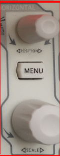
The HORIZONTAL knob will translate the waveform horizontally. The time translated horizontally is shown on the top right in ms(microseconds) by default. Turning this knob clockwise will move it right, and turning it counter-clockwise will move it left. Pressing down on the knob will reset the position of the waveform back to the origin.
The MENU button will display a series of options on the right side of the screen, such as adding a time delay.
The SCALE knob is essentially a zoom feature. Turning this will change the time scale along the x-axis to show a shorter or longer period. Turning this knob clockwise will stretch it horizontally, and turning it counterclockwise will compress it horizontally. Pressing down on this knob will activate the zoom feature. A window appears showing the zoom.
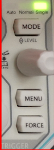
In the TRIGGER section on the faceplate, the MODE button will set the trigger mode of the oscilloscope to Auto, Normal or Signal.
The LEVEL knob will determine when the trigger gets activated. Turn clockwise to increase the level and turn counterclockwise to reduce the level. The trigger level is shown in the bottom left corner of the screen. Pressing down will reset the trigger back to zero.
The MENU button will start the trigger menu on the right side of the screen. The menu includes a type, source, slope, and sweep trigger. The type will let the user choose what triggering method is used, source will let the user choose which channel is being sourced from, the slope will let the user choose if the oscilloscope is triggered on a rising/falling clock edge, and time will let the user choose between single, auto or normal.
The FORCE button will manually force the trigger to happen.
- The HELP button will show a menu on the screen with the option to choose different descriptions of each part of the oscilloscope.
The PRINT button will save the current display on a USB stick if inserted in the slot.
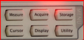
Pressing the MEASURE button will open the measurement menu. The user can change which channel is being measured, enable the frequency counter, or enable the statistics button to show different frequencies, such as the current, average, or peak values.
Pressing the ACQUIRE button will show a menu where the user can change the acquisition mode, sin(x)/x and memory depth of the oscilloscope.
The STORAGE button enters the file storage option, where files can save as different types on the external USB or the oscilloscope’s memory storage.
The CURSOR button will display different modes for using a cursor: manual, track, auto and XY.
The DISPLAY button will show the options for display type, persistence time, grid type and brightness.
The UTILITY button will show options such as IO setting, sound, language, pass/fail, waveform record, and system self-calibration.
The clear button will CLEAR the current waveforms on the screen.
The AUTO button will automatically adjust the vertical and horizontal scale and set the triggering based on the input.
The RUN/STOP button will enable or disable the waveform. The waveform is enabled if the button is green and will move in real-time. If the button is red, the waveform is paused when pressed and will show a still image of the waveform at that time.
The single trigger mode will be activated if the SINGLE button is pressed. Pressing the SINGLE button will activate the single trigger mode.
Pressing the FORCE button will force the trigger to happen.

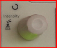
The intensity knob will adjust the intensity of the signal from 0% to 100% on the screen. Pressing down on this button will reset it back to 60%. The intensity knob can navigate the menus if the MENU button is activated. Turning the knob clockwise will increase the intensity, and counterclockwise will decrease it.
The first and second sets of buttons to select different menu options.

