Optimizing the Design
Creating the Design Study
With our failure criteria for our model now understood, we can now begin to make optimizations to the model to achieve more desirable values and maximize bracket strength while minimizing weight. While manually changing model geometry is an option, the “Design Study” feature in SOLIDWORKS can help with the optimization process.
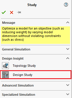
Creating a design study using the “New study’ option like the previously completed studies. Selecting OK will open a table that will have inputs for variables, constraints & goals.
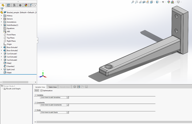
Adding Variables
The “Variables” option in the study window allows you to add the parameters that you would like for your study to try to optimize, such as the model dimensions. Parameters can be added by selecting the “Add Parameters” option in the “Variables” dropdown menu:

Selecting “Add Parameters” should next open the Parameters window:
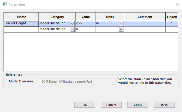
The study will attempt to optimize the bracket dimensions by increasing or decreasing them. In the case of the bracket I’ve selected the bracket arm as well as the bracket arm width & height to be chosen parameters.
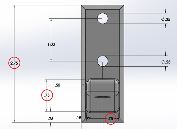
To add the dimensions to the parameter list, click the black parameter box and select the dimension from the visual window on the bracket that you wish to add as a parameter. Once all desired parameters are added, the window should appear similar to the following:
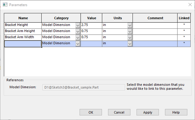
With all the desired parameters chosen, click apply to add the parameters to the study window and OK to exit the parameter window. The variables (if not already in the variable option in the design window) can now be added using the dropdown menu.
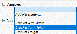
Having added the variables, we can now select how we wish for the study to optimize the selected dimensions. This can be dictated by the options directly next to the variable name. Here there are 3 options; “Range with Step”, “Discrete Values” & “ Range”. Here we will choose “Range with Step”, which optimizes the bracket by assigning a maximum, minimum and step value for each variable that the program will iterate through for each scenario. The maximum and minimum will determine the range that the iterations will start and stop with while the step value will dictate how much the parameter value will increase by when the design iterates. In the table below, the optimization will start with the height at 1.375 inches and repeatedly do iterations by increasing the height each time by 0.25 inches until it reaches the maximum of 4.125 inches. The same 0.25 inch step will be used for the bracket arm & height except with a range of 0.375-1.125 inches as seen below:

This process can be completed using multiple parameters and iterated with max, min & step values all of your choice, so it is up to you to decide what geometry is best suited for optimization. However, doing multiple iterations with smaller steps will add a drastic increase in your total number of iterations which can prolong the optimization process.
Adding Constraints
With all of our variables established, constraints for the optimization can now be added. With constraints, the type of data that will be analyzed during the optimization will be chosen. Optimization parameters can be added just as the variable parameters were using the appropriate dropdown menu:

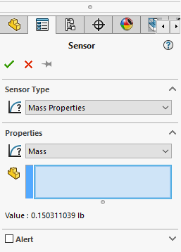
Selecting the “Add Sensor” option will open up the Sensor property window:
Using the constraints menu, we can define the constraints that we wish for our optimizations & iterations to adhere to. In the case of the bracket, since were are trying to ensure that our bracket does not fail but ensuring the shear stresses on the bracket do not exceed the material’s ultimate strength of 73.7 MPa, we will add a constraint to monitor the shear stresses on the bracket to make sure they stay below the ultimate strength.
Under sensor type, we will choose “Simulation Data” and “Stress” & “von Mises Stress” under the “Results” & “Components” section in “Data Quantity”.
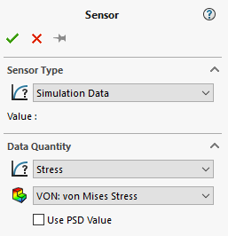
Finally, since we do not want our optimizations to create stress values greater than the yield stress, we set our Criterion for entities as “Model Min” under “Properties”.
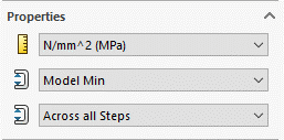
Clicking OK in the top left corner will implement the changes to constraints, giving the design window as seen below:

Again, we wish to ensure that the von Mises stress for the whole bracket does not exceed the material’s ultimate strength, therefore we will assign the “Max” value for the stress sensor under “Constraints” to be 73.7 MPa.

As well ensure that the stress sensor is applying to the correct static study (in our case the study being “Bolt Load”).
Adding Goals
Finally we want for the bracket to be as mass efficient as possible, therefore a goal for the model should be to minimize the mass. This goal can be implemented by adding a sensor using the goal feature in the variable view table exactly as was done in the previous steps. In the “Sensor” property window, mass properties if not already selected and under properties select the bracket in the “Entities to Monitor” box.
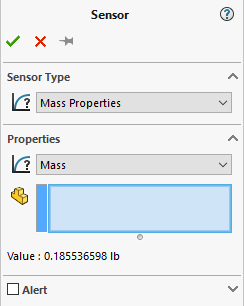
With all of the settings implemented as described below, the variable view table will appear as follows.

Running & Verifying the Optimization
With the variable view table now completely filled in and matching our criteria, we can verify that we have set up our optimization scenario correctly and any changes that you may need to make to any of the parameters can be made in this table. With everything verified, we can now execute our optimization by selecting the “Run” button.
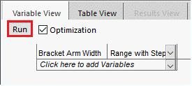
As stated earlier, depending on the number of scenarios that you have due to the number of steps & variables you have this may be a lengthy process, as for each iteration the results run & mesh will need to be re-ran each time due to the changing model dimensions. Be wary about how many steps you wish to include for each variable. If you have a large number of variables, consider implementing larger steps for each one and vice-versa. For this particular study, running the study produced the following result across the 192 scenarios. In the bracket optimization, none of the scenarios gave a stress value that satisfies the materials yield stress therefore the optimization failed. However adding additional dimensional parameters to iterate with would most likely provide an optimal set of dimensions that fall under the given criteria and is highly recommended in the case where a design study has failed. Therefore, our model will most definitely need a redesign of some sort such as the inclusion of more supports.

Topology Optimization Alternatively, one of the more advanced methods of optimizing a model in SOLIDWORKS is the Topology optimization. A topology optimization is a computerized mathematical method used to determine and allocate material within a specified domain. In the case of SOLIDWORKS, a topology optimization could be used to reduce the amount of unneeded material in the bracket that does not provide sufficient structure support or generate support structure material to increase structural integrity. Topology studies can be created just like the previously mentioned design 7 static studies by selecting “New Study” under the SOLIDWORKS Simulation tab. For more information on how to properly setup a topology study, click the youtube video link here.