Understanding Strength & Failure
Before starting with creating the analysis, it’s important to first talk about some of the basic solid mechanics principles that are involved with these analyses.
Deformation
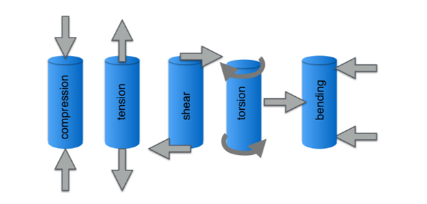
Deformation is described as the changing in size and shape of an object. In an engineering context it is used to measure the failure of an object. In the case of the tutorial, the deformation of the bracket is what will be measured to determine the behavior of the bracket in how and when it will fail. The deformation of an object & external forces creating the deformation can be represented using stress & strain. Strain is the internal change of an infinitesimally small cube of area on an object, whereas stress is defined as the measure of internal resistance of a material from a force applied to it per cross sectional area.

There are also two forms of deformation: Elastic & Plastic deformation. Elastic deformation or temporary deformation is when a material is compressed, stretched, or bent but can return to its original state before deformation occurs. Think of elastic deformation as a trampoline. As you bounce on it, the trampoline mesh & springs holding the mesh will begin to bend as more of your weight is placed on the trampoline. However, once you are airborne the trampoline mesh & springs can return to how it was initially with no changes to the mesh. Plastic deformation is when a material is compressed, stretched, or bent but instead experiences some form of permanent deformation and is not able to return to its original shape. An example of plastic deformation would be stretching the trampoline springs too hard. Up to a certain threshold, when jumping on the trampoline the springs are stretched and can return to its initial shape with no changes. However if the spring were stretched really hard, it would be permanently stretched some amount and would be unable to return to the original shape, meaning that the mesh of the trampoline would experience some amount of sagging.
*VIDEO LINK HERE*
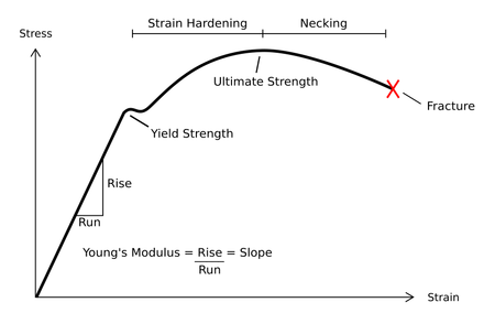
This threshold or “yield point” of when an object transitions from elastic to plastic deformation can be represented by the Stress-strain curve, as shown in the figure below.

On the stress-strain curve we can see the initial section of the curve is a straight line up until it reaches a peak. This region is called the elastic region and it’s the region in which an object will experience elastic deformation & where the trampoline will always return to its original state. The peak of this linear curve is called the yield point and it’s at this point where our part structure will begin to “yield” and start transitioning from elastic to plastic deformation. This is the point where the trampoline springs would begin to experience stretching. The stress value at this point is used in failure analysis, also known as “yield strength”, which will be our most important value in our simulation that we will conduct later. As an object continues to experience more stress it will begin to elongate as it enters the “Strain Hardening” region where it will reach its maximum sustainable stress value also known as “ultimate tensile strength (UTS)”. It’s in this region where the trampoline springs have started stretching and are now beginning to fail. Once past the point of ultimate tensile strength, the object will enter the necking region where the part will continue to elongate until it breaks apart or fractures. At this point, the spring has stretched more than it’s able to handle and the spring will now break.
One more important stress value that will be needed for this simulation is flexural strength, which is the stress in a material before it experiences any flexing. This flexing comes from a part being put in compression, which causes the part to start deflecting. The use of flexural strength will be further explained in the material properties creation & bending analysis section of the tutorial.
Shear Stress & Failure Due to Sheer
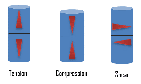
When discussing loading failure, our interest is on how the model will fail as the load is applied to it and its behavior when it does fail. In our case, we are simulating a 200 lb. applied to the model bracket and analyzing how our bracket will behave with this applied load, which we will do by analyzing how stress is distributed in the model. There are two forms of stress: normal stress and shear stress. Normal stress is stress that acts normal to the surface of a body whereas shear stress acts parallel to the body. From the normal & shear stress values that can be calculated for an applied load acting on a model the Von Mises stress can be calculated, which is the value(s) responsible for determining whether the material will fail or not.

Buckling & Failure Due to Buckling
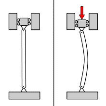
Another study we should also be concerned about is a buckling study since we may also want to observe the brackets buckling behavior when put under load. Buckling is the deformation of a structure that occurs when for example a beam is placed under a compressive load or a load that develops shear stress, causing the beam to “buckle”. For an ideal column under load (typically a fixed-fixed long slender beam), buckling will not occur until the load has climbed to a specific value called the critical load, at which point the beam will laterally deflect, similar to the image shown below. Unlike failure due to shear, “buckled” structures can continue to support a load after having failed due to buckling but cannot sustain any additional load.

Although in the case of our bracket there is no “direct” axial load as in the picture causing the bracket to compress, the load acting at the hole from the eye hook is supplying both tension and compression to the top and bottom surfaces of the bracket arm respectively like the upward bending of the table shown in the image below.

Using SOLIDWORKS Simulation, we can observe the behavior of the beam under load and visually represent how the bracket will fail under load, as well as the load that would cause the bracket to fail due to buckling.