Refining a Mesh
Reasons to Refine
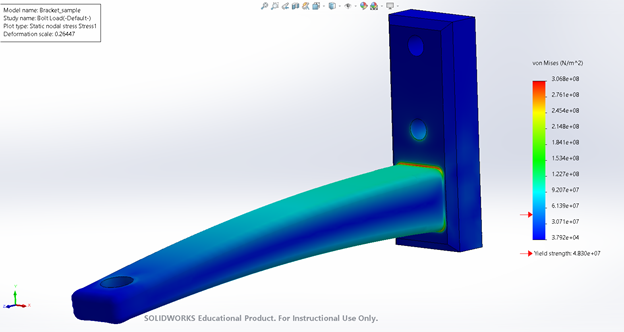
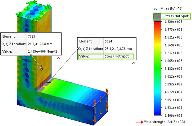
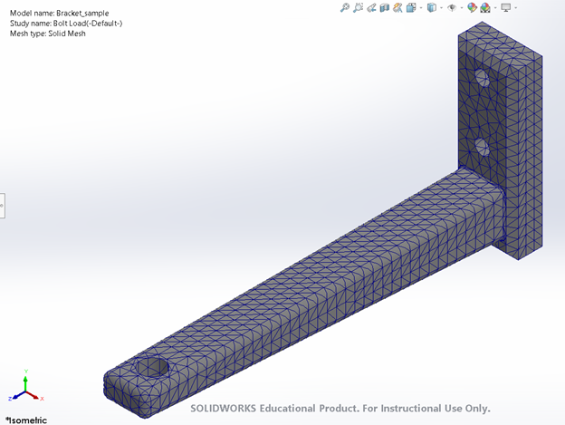
As mentioned in the initial meshing section, to attain better and more accurate results we can choose to further refine the mesh where necessary. Refining the mesh is an important step in any study and can take repeated iterations to complete. However, refining the mesh based on study results can lead to much more accurate final results as you will understand from your initial results where areas of interest on your model may be.
Adding Refined Meshes in Specific Locations
However with the mesh rebuilt we get the mesh with a new issue, as now there is only a single row of mesh elements that are on the new fillet.
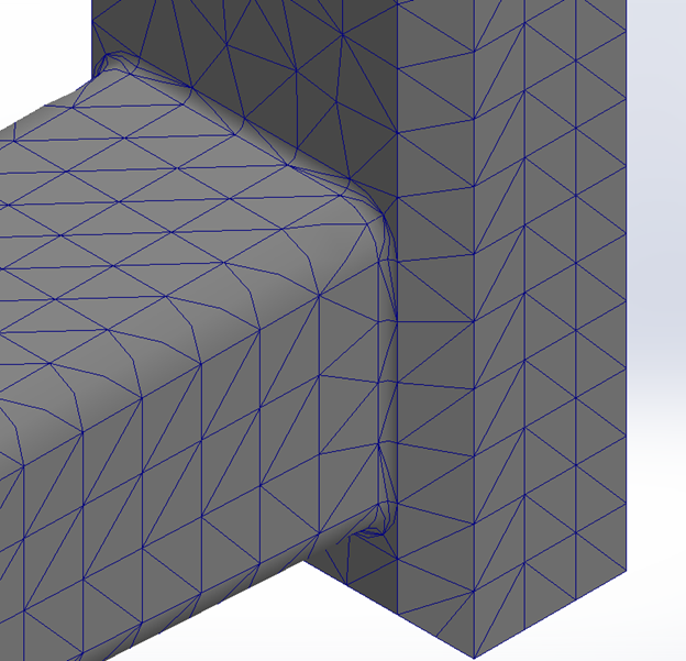
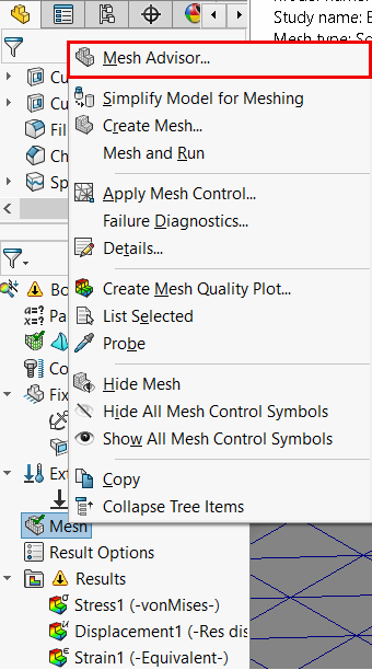
Only having a single row of elements on the fillet could lead to some inaccuracies in our results, so increasing the number of elements on the fillet will fix this issue. This can be done by selecting “Apply Mesh Control ‘’ in mesh options and applying a finer mesh (of your choosing) to the fillet as shown below.
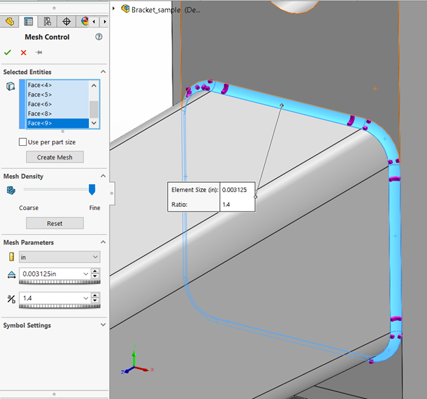
As well, a finer mesh should also be considered in areas of importance on a model. In the case of the bracket, the bolt holes and the mounting hole will be our areas of interest since they’ll be fixtures or experiencing the load in some form. Therefore, we will also apply the same finer mesh to these areas.
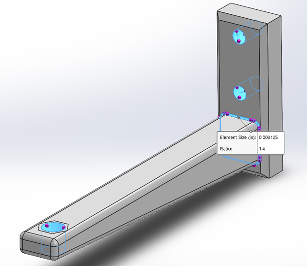
Hitting OK, we should see a finer mesh at the fillet now compared to the rest of the part, giving the final mesh as shown below. With these adjustments, your model overall should see a significant improvement in result quality and accuracy. An important final note is that whenever any change is made to the model mesh, the model will have to be re-meshed in order to apply the changes by just reselecting “Create Mesh” and reapplying the mesh with your previously selected or desired mesh quality settings.
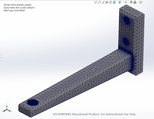
We can now re-run the study to obtain new results with much more accurate stress distribution readings:
